My Haas Welcome,
!
Haas Tooling MyHaas/HaasConnect Sign In Register Haas Tooling MyHaas/HaasConnect Sign Out Welcome, My Machines Latest Activity My Quotes My Account My Users Sign Out
Find Your Distributor
  1. Select Language
    1. English
    2. Deutsch
    3. Español - ES
    4. Español - MX
    5. Français
    6. Italiano
    7. Português
    8. Český
    9. Dansk
    10. Nederlands
    11. Magyar
    12. Polski
    13. Svenska
    14. Türkçe
    15. 中文
    16. Suomi
    17. Norsk
    18. الإنجليزية
    19. български
    20. Hrvatski
    21. Ελληνικά
    22. Română
    23. Slovenský
    24. Slovenščina
    25. 한국어
    26. 日本語
    27. Українська
  • machines Main Menu
    • Vertical Mills
      Vertical Mills
      Vertical Mills View All
      • Vertical Mills
      • VF Series
      • Universal Machines
      • VR Series
      • VP-5 Prismatic
      • Pallet-Changing VMCs
      • Mini Mills
      • Mold Machines
      • High-Speed Drill Centers
      • Drill/Tap/ Mill Series
      • Toolroom Mills
      • Pocket Mill
      • Compact Mills
      • Gantry Series
      • SR Sheet Routers
      • Extra-Large VMC
      • Double-Column Mills
      • 3+2 Positioning Machines
    • Multi-Axis Solutions
      Multi-Axis Solutions
      Multi-Axis Solutions View All
      • Multi-Axis Solutions
      • Y-Axis Lathes
      • 5-Axis Mills
    • Lathes
      Lathes
      Lathes View All
      • Lathes
      • ST Series
      • Dual-Spindle
      • Box Way Series
      • Toolroom Lathes
      • Chucker Lathe
      • Pocket Lathe
      • Haas Bar Feeders
    • Horizontal Mills
      Horizontal Mills
      Horizontal Mills View All
      • Horizontal Mills
      • 50-Taper
      • 40-Taper
    • Rotaries & Indexers
      Rotaries & Indexers
      Rotaries & Indexers View All
      • Rotaries & Indexers
      • Rotary Tables
      • Indexers
      • 5-Axis Rotaries
      • Extra-Large Rotaries
    • Special Series
      Special Series
      Special Series View All
      • Special Series
      • EU_Series_Redirect
    • Automation Systems
      Automation Systems
      Automation Systems View All
      • Automation Systems
      • Mill Automation
      • Lathe Automation
      • Automatic Parts Loaders
      • Automation Models
    • Desktop Machines
      Desktop Machines
      Desktop Machines View All
      • Desktop Machines
      • Desktop Mill
      • Desktop Lathe
      • Control Simulator, Standard
      • Control Simulator, Premium
    • Shop Equipment
      Shop Equipment
      Shop Equipment View All
      • Shop Equipment
      • Knee Mill
      • Haas Manual Lathes
      • Haas Saws
    • Fabrication Machines
      Fabrication Machines
      Fabrication Machines View All
      • Fabrication Machines
      • Laser Cutting Machines
      • CNC Press Brakes
    • QUICK LINKS Special Series  Special Series 
      EU SERIES EU SERIES BUILD & PRICE | PRICE LIST BUILD & PRICE | PRICE LIST In-Stock Machines In-Stock Machines WHAT’S NEW WHAT’S NEW YOUR FIRST CNC YOUR FIRST CNC
      SHOPPING TOOLS
      • Build & Price a Haas
      • Price List
      • Available Inventory
      • CNCA Financing
      WANT TO TALK TO SOMEONE?

      A Haas Factory Outlet (HFO) can answer your questions, and walk you through your best options.

      CONTACT YOUR DISTRIBUTOR >
  • Options Main Menu
    • The Haas Control Value Option Packages
      Value Option Packages
      Value Option Packages View All
      • Value Option Packages
    • Product Image Spindles
      Spindles
      Spindles View All
      • Spindles
    • Product Image Tool Changers
      Tool Changers
      Tool Changers View All
      • Tool Changers
    • Product Image 4th- | 5th-Axis
      4th- | 5th-Axis
      4th- | 5th-Axis View All
      • 4th- | 5th-Axis
    • Product Image Turrets & Live Tooling
      Turrets & Live Tooling
      Turrets & Live Tooling View All
      • Turrets & Live Tooling
    • Product Image Probing
      Probing
      Probing View All
      • Probing
    • Haas Chip & Coolant Management Chip & Coolant Management
      Chip & Coolant Management
      Chip & Coolant Management View All
      • Chip & Coolant Management
    • The Haas Control The Haas Control
      The Haas Control
      The Haas Control View All
      • The Haas Control
    • Product Image Product Options
      Product Options
      Product Options View All
      • Product Options
    • Product Image Tooling & Fixturing
      Tooling & Fixturing
      Tooling & Fixturing View All
      • Tooling & Fixturing
    • Product Image Workholding
      Workholding
      Workholding View All
      • Workholding
    • Product Image 5-Axis Solutions
      5-Axis Solutions
      5-Axis Solutions View All
      • 5-Axis Solutions
      • 5 Easy Steps to 5-Axis
    • QUICK LINKS Special Series  Special Series 
      EU SERIES EU SERIES BUILD & PRICE | PRICE LIST BUILD & PRICE | PRICE LIST In-Stock Machines In-Stock Machines WHAT’S NEW WHAT’S NEW YOUR FIRST CNC YOUR FIRST CNC
      SHOPPING TOOLS
      • Build & Price a Haas
      • Price List
      • Available Inventory
      • CNCA Financing
      WANT TO TALK TO SOMEONE?

      A Haas Factory Outlet (HFO) can answer your questions, and walk you through your best options.

      CONTACT YOUR DISTRIBUTOR >
  • Why Haas Main Menu
      Discover the Haas Difference
    • Why Haas
    • MyHaas
    • Education Community
    • Industry 4.0
    • Haas Certification
    • Customer Testimonials
  • Service Main Menu
      Welcome to Haas Service
      SERVICE HOME Operator’s Manuals How-To Procedures Troubleshooting Guides Preventive Maintenance Haas Parts Haas Tooling Videos
  • Videos Main Menu
  • Main Menu
    • View All
    • View All
    • View All
    • View All
      • HTEC Curriculum Support
      • Haas Value Option Packages (VOP) Journey
    • View All
      • Haas 10 kg Cobot Package
      • Cobot Kits
      • DC-1 Drill Center
      • CNC Sales News
      • Do More With Your Haas
    • View All
    • View All
      • contact-us-test
      • 4 - AUTOMATION SYSTEMS
      • Carousel-V2
      • expert test
      • Demo_Day_Trident-test
      • Link Test
      • image-sale-tag-test
      • article-list-test
      • Haas 25 kg Robot Package
      • test-algolia-page
    • View All
    • View All
    • View All
    • View All
      • calc-test
    • View All
    • QUICK LINKS Special Series  Special Series 
      EU SERIES EU SERIES BUILD & PRICE | PRICE LIST BUILD & PRICE | PRICE LIST In-Stock Machines In-Stock Machines WHAT’S NEW WHAT’S NEW YOUR FIRST CNC YOUR FIRST CNC
      SHOPPING TOOLS
      • Build & Price a Haas
      • Price List
      • Available Inventory
      • CNCA Financing
      WANT TO TALK TO SOMEONE?

      A Haas Factory Outlet (HFO) can answer your questions, and walk you through your best options.

      CONTACT YOUR DISTRIBUTOR >
  • Haas Tooling Main Menu
  • Haas Service Parts Main Menu

My Haas Welcome,
!
Haas Tooling MyHaas/HaasConnect Sign In Register Haas Tooling MyHaas/HaasConnect Sign Out Welcome, My Machines Latest Activity My Quotes My Account My Users Sign Out
Find Your Distributor
  1. Select Language
    1. English
    2. Deutsch
    3. Español - ES
    4. Español - MX
    5. Français
    6. Italiano
    7. Português
    8. Český
    9. Dansk
    10. Nederlands
    11. Magyar
    12. Polski
    13. Svenska
    14. Türkçe
    15. 中文
    16. Suomi
    17. Norsk
    18. الإنجليزية
    19. български
    20. Hrvatski
    21. Ελληνικά
    22. Română
    23. Slovenský
    24. Slovenščina
    25. 한국어
    26. 日本語
    27. Українська
×

Search Results

Web Pages

Images

    • <
    • 1
    • >

BMT65/75 - Turret - Piston - Replacement - AD0425

Service Home How To Procedures BMT65/75 - Turret - Piston - Replacement - AD0425

BMT65/75 - Turret - Piston - Replacement - AD0425

- Jump to Section - 1. Introduction 2. BMT65/75 - Turret Piston - Replacement (15 steps) 3. BMT65/75 Live Tooling Drive Alignment (3 steps) 4. Verification (1 step) Back to Top
Recently Updated Last updated: 05/13/2025

BMT65/75 Turret - Piston - Replacement


AD0425

Revision A - 05/2025

Introduction

This procedure should be referenced when replacing the BMT65/75 Live Tool torque arm, turret piston cover, turret piston, or turret piston seals. 

This document and service kit applies to the following part numbers:

  • 93-2938 BMT LIVE TOOL TORQUE ARM SVC KIT (Skip steps 6-11).
  • 93-2939 BMT TURRET PISTON COVER SVC KIT (Skip steps 9).
  • 93-2941 BMT TURRET PISTON SVC KIT (Use entire document).
  • 93-3874 BMT65 PISTON SEAL SVC KIT (Use entire document). 

BMT65/75 - Turret Piston - Replacement

1

Index the turret to tool number 1.

Turn off the main air supply to the machine.

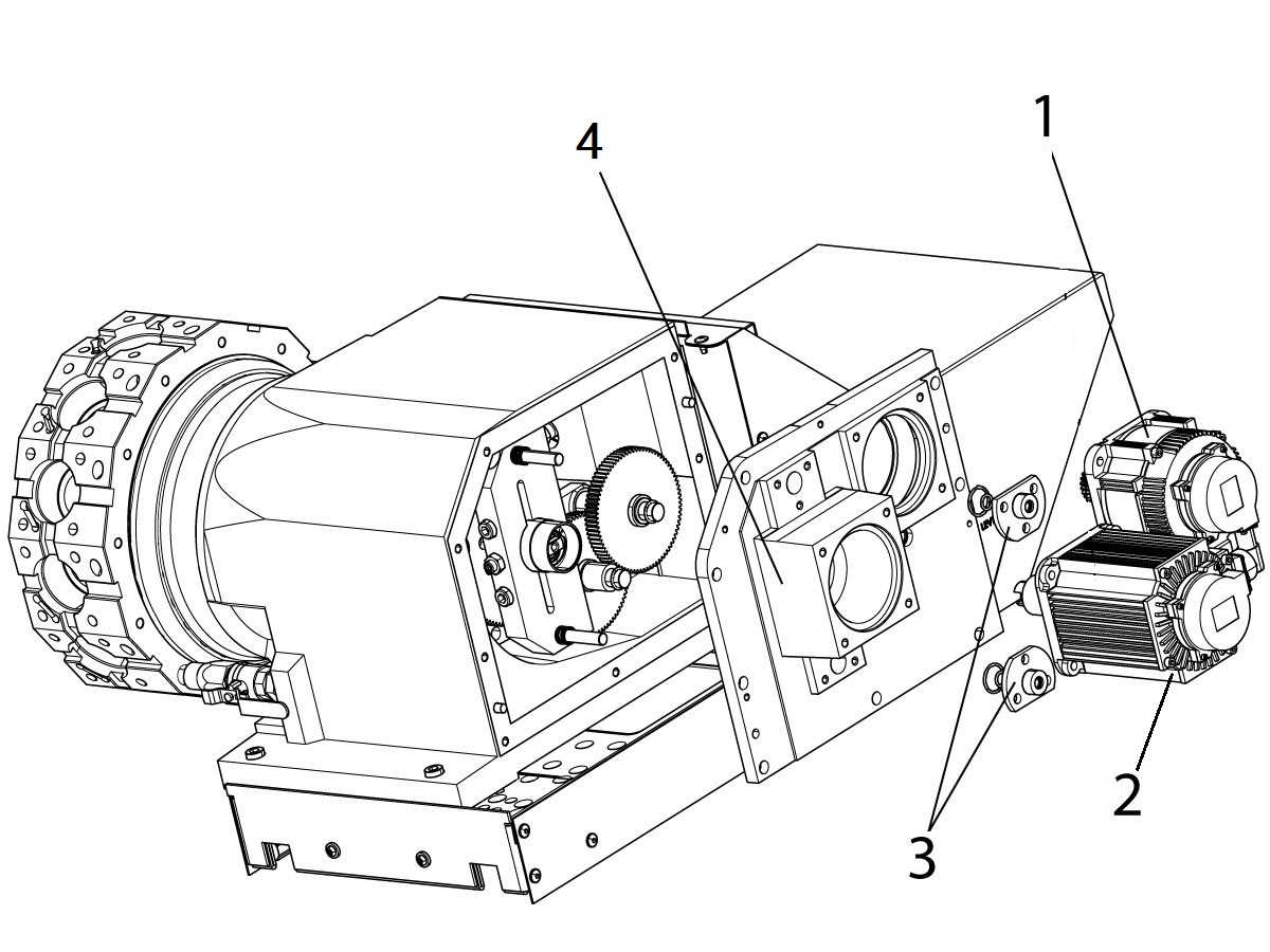
Remove the following items in this order:

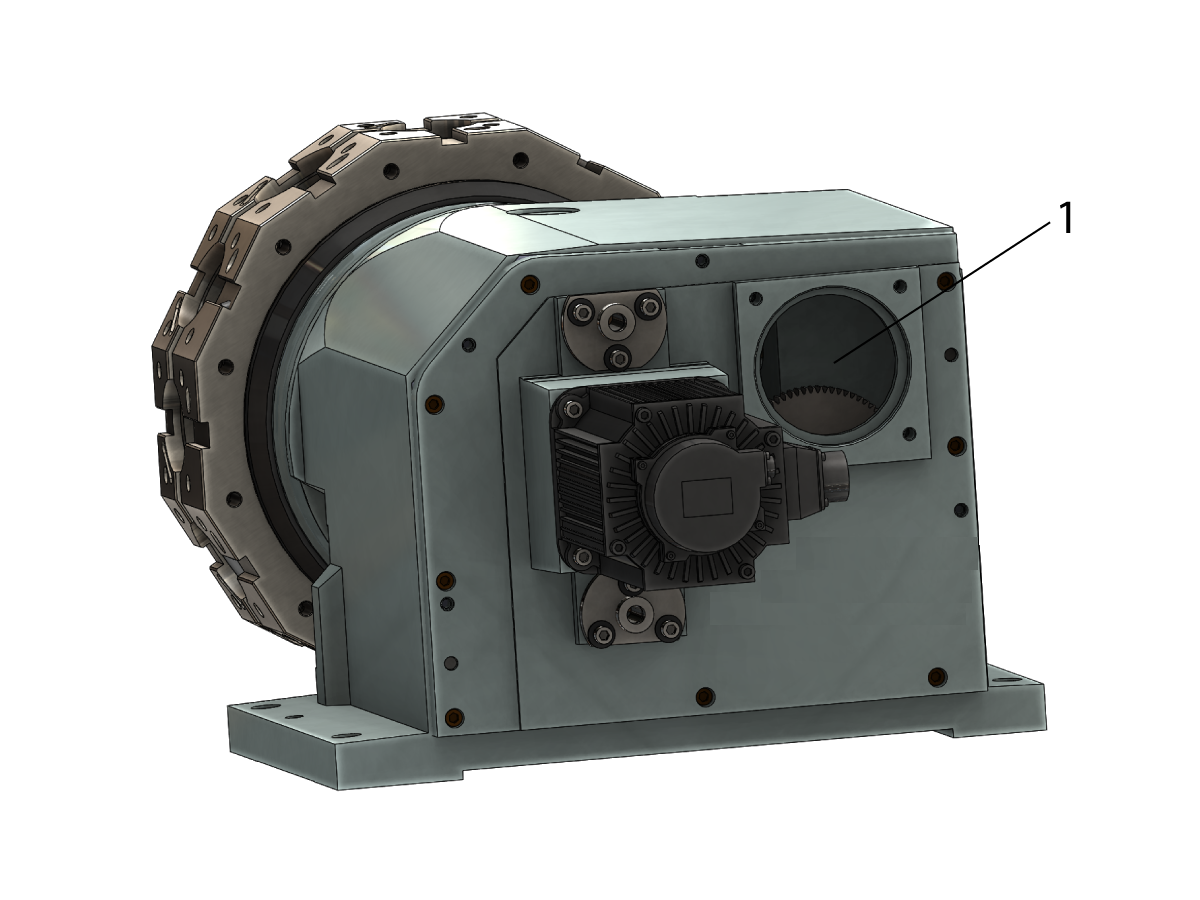
  • The turret servo motor [1].
  • If machine is equipped with the live tooling, remove the live tooling servo motor [2] and the top and bottom alignment bushings [3].
  • The rear turret gearbox cover [4] (lubricant/oil  will drain).

NOTE: Before removing the rear cover tape a trash bag under the gearbox to catch the lubricant.

2

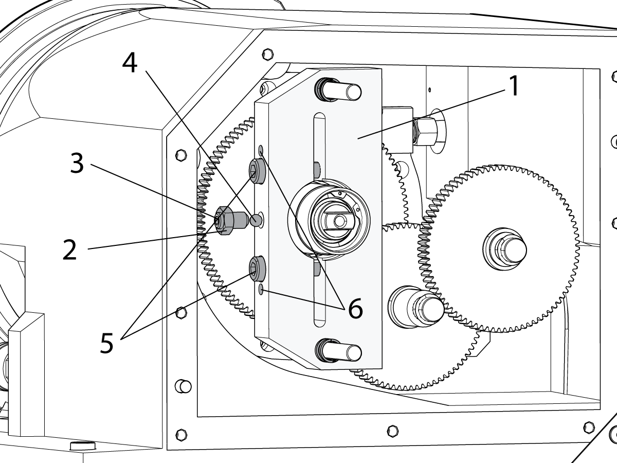
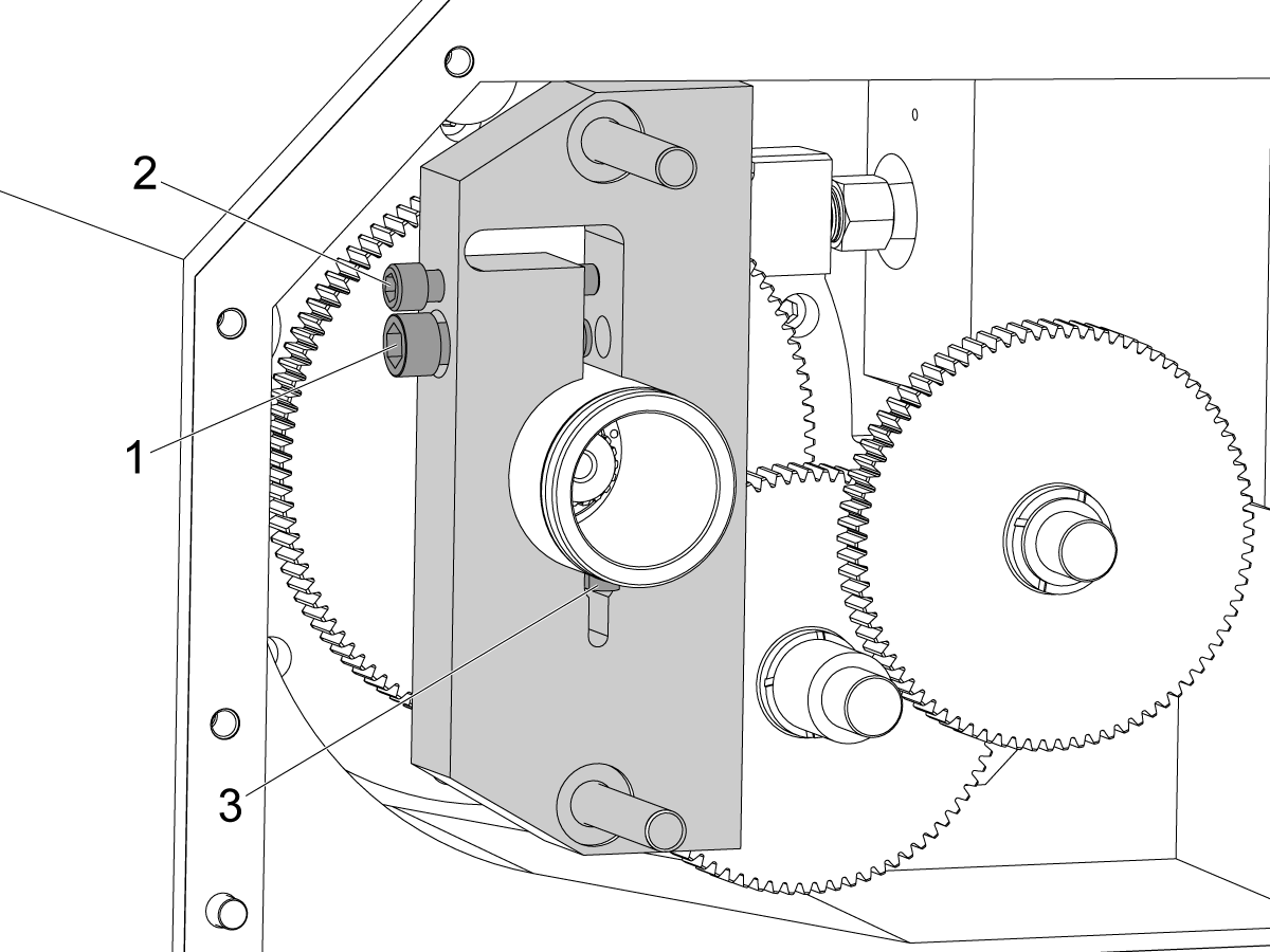
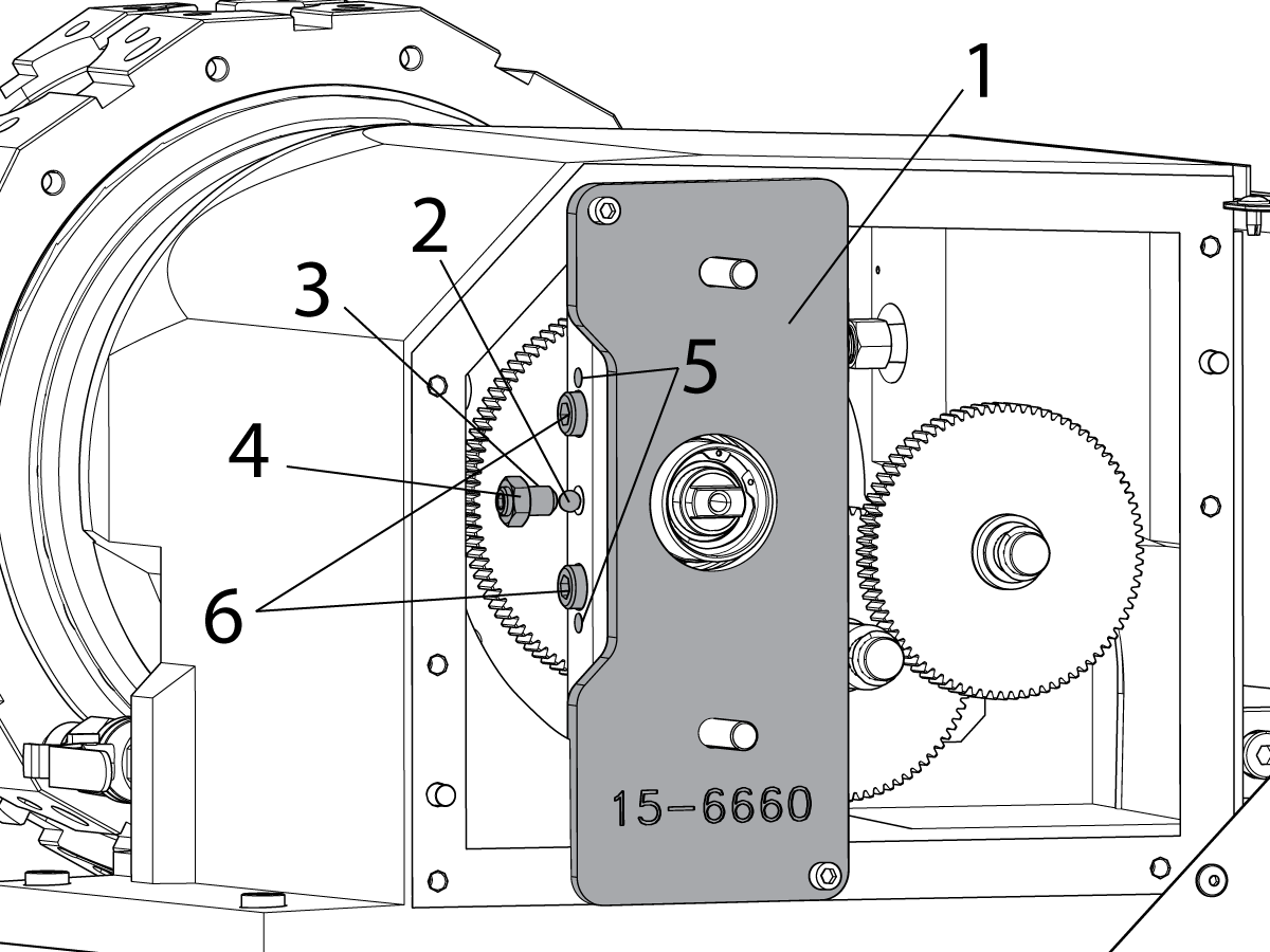
If equipped with live tooling, remove the torque arm [1] with a set screw and ball bearing in the following order:

  • Loosen the jam nut [2].
  • Remove the set screw [3] and steel ball [4].
  • Loosen the two clamp bolts [5].

 NOTE : If needed, install two 5/16-18 bolts in the jack screw holes [6] next to the clamp bolts. Apply just enough torque to spread the torque arm so it can slide off the torque tube.

 NOTE: In the event of a live tool crash the torque arm may be difficult to remove. A pulley puller may be used. If the torque arm still cannot be removed cut it off the torque tube with a grinder. If a grinder was used remove the gears from the turret housing, thoroughly clean them and the turret housing.

Remove the torque arm.

Remove the snap ring from the torque tube.

3

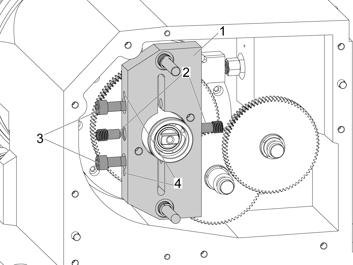
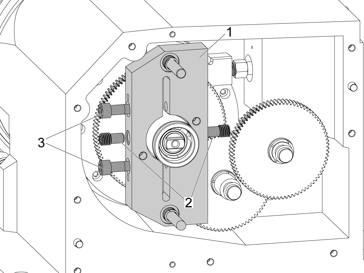
To remove the torque arm [1] with set screws, remove the following items in this order:

  • Remove the set screws [2]
  • Loosen the two clamp bolts [3].

Remove and discard the torque arm.

 NOTE : If the set screws are difficult to remove, use a blow torch to apply localized heat to the set screws to soften the loctite.

 NOTE : If needed, install two 5/16-18 bolts in the jack screw holes [4] next to the clamp bolts. Apply just enough torque to spread the torque arm so it can slide off the torque tube.

 NOTE : In the event of a live tool crash the torque arm may be difficult to remove. T-0133 BMT TORQUE ARM PULLER can be used or a pulley puller. If the torque arm still cannot be removed cut it off the torque tube with a grinder. If a grinder was used remove the gears from the turret housing and thoroughly clean them and the turret housing.

4

Torque arm with set screws:

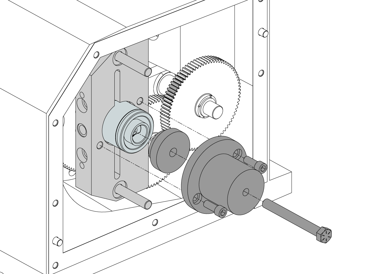
T-0133 BMT TORQUE ARM PULLER is used to remove the torque arm from the torque tube.

Install the stop to the torque tube.

Install the puller to the torque arm and install the jack screw to the puller.

Tighten the jack screw to remove the torque arm from the torque tube.


5

To remove the torque arm with the keyway, remove the following items in this order:

  • Remove the clamp screw [1]
  • Install a 3/8-16 bolt[2] in the jack screw hole next to the clamp bolt. Apply just enough torque to spread the torque arm so it can slide off the torque tube.

 NOTE: In the event of a live tool crash the torque arm may be difficult to remove. A pulley puller may be used. If the torque arm still cannot be removed cut it off the torque tube with a grinder. If a grinder was used remove the gears from the turret housing, thoroughly clean them and the turret housing.

Remove the torque arm.

Remove the key[3] from the torque tube.

Remove the snap ring from the torque tube.

6

Unplug the red and green air lines from the turret solenoid in the CALM lube panel.

7

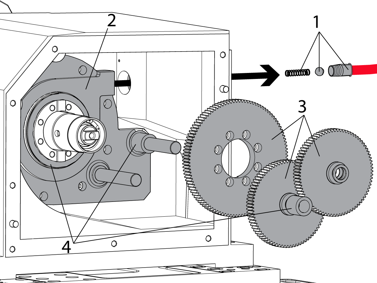
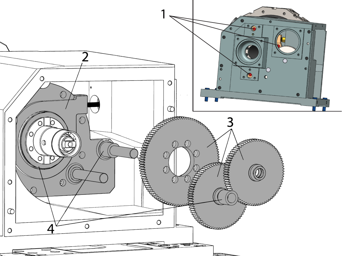
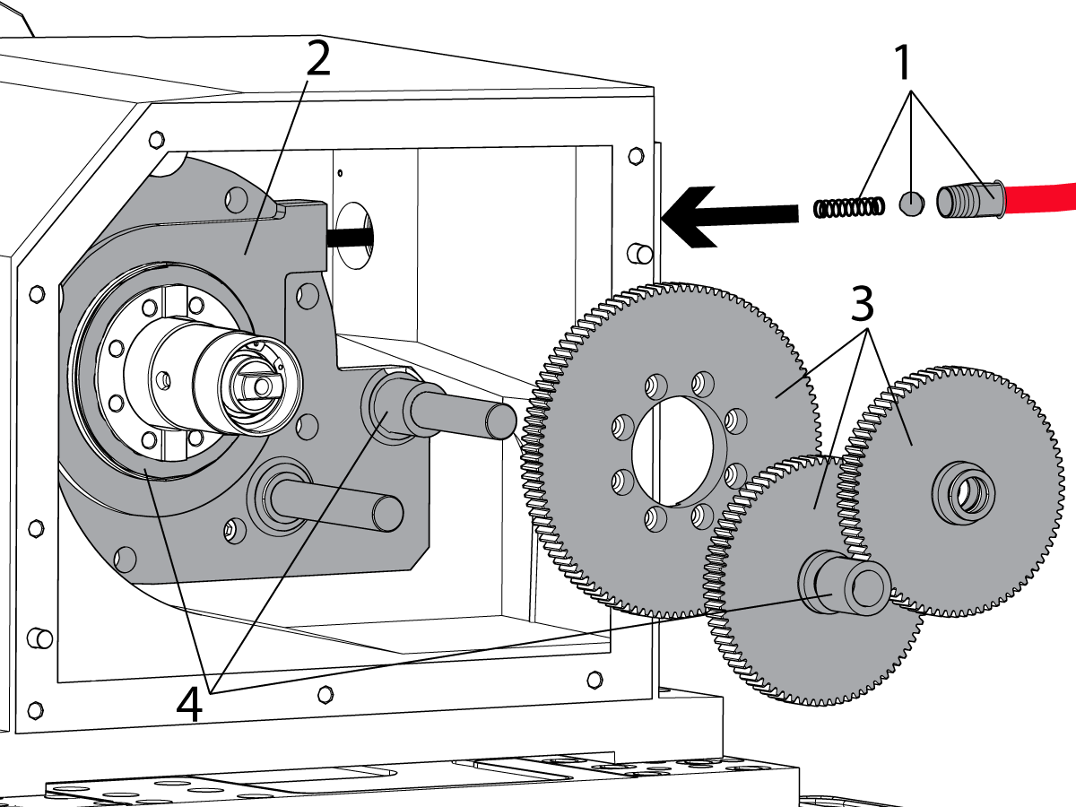
Remove the air tube fitting, ball, and spring [1] from the fitting on the piston cover [2].

Remove the drive gears [3], and spacers [4]. The main gear is under spring tension. You will feel this as you remove the bolts.

 Caution: The main drive gear bolted to the turret shaft prevents the turret and turret shaft assembly from being removed. Use caution not to pull on the turret while the gear is off or it may come out of the housing.

Remove the piston cover [2]. The cover has a low spring tension against it, you will feel this as the bolts are removed.

8

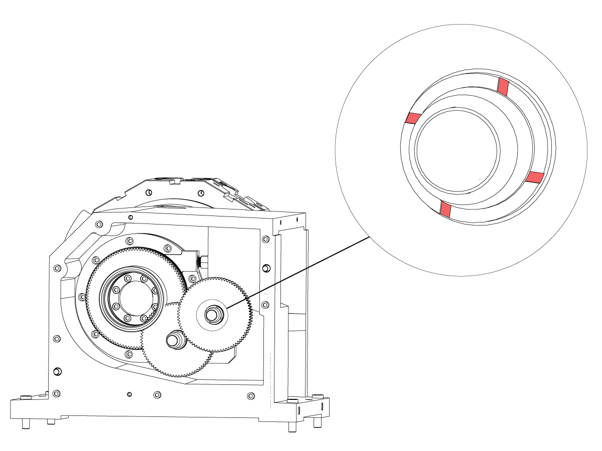
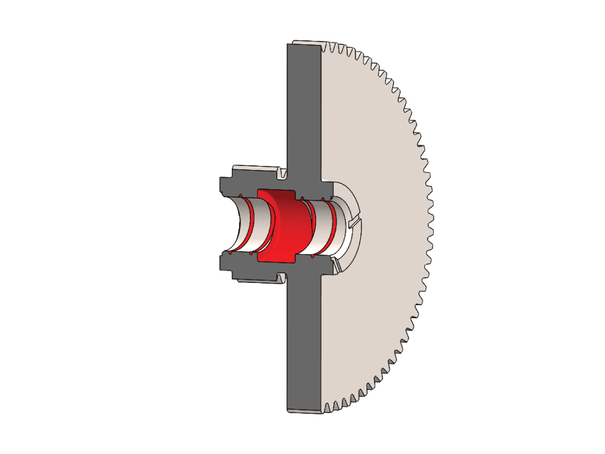
If your idler gears do not have the four machined grooves in the face (highlighted in red), then replace both of them with the updated part number 20-6645A. 

9

Thread (2) 5/16-18 bolts into the piston to pull on and remove the piston [1]. 

If the piston was leaking, replace the existing quad ring and O-ring with the ones from the 93-3874 kit. Apply 99-1792 grease to the rings.

Inspect piston, thrush washers, and springs [2] for damage. Replace if needed from the 93-2941 kit. If any part is verified as usable, clean and re-grease it, using the 99-1792 grease in the 93-3874 kit, before reinstalling.

Clean the bore and apply a light layer of grease in the bore, on the shaft, and the piston seals (if not already re-greased). 

Install the piston. Align the pin [3] on the back side of the piston with the hole in the casting.

10

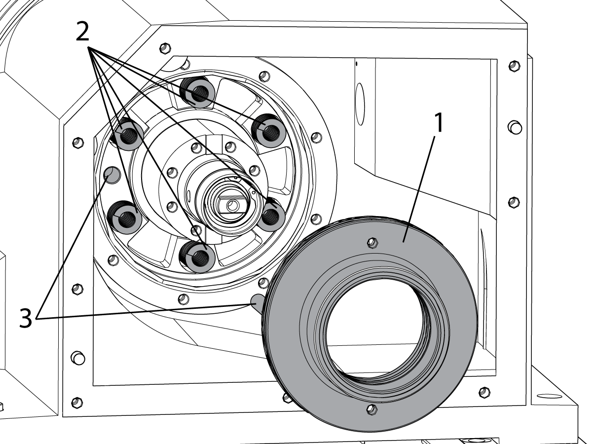
Install the piston cover [2], but leave the bolts just loose enough for the cover to be adjusted within its mounting holes. The piston cover is under spring tension. You will feel tension as you tighten the bolts on the cover.

Install the gear spacers [4] and gears [3]. The turret shaft is under spring tension. You will feel tension as you tighten the bolts on the gear.

Install the back cover and tighten the bolts. Now tighten the three piston cover bolts you can reach [1]. 

Unclamp the turret. Spin the gears inside the gearbox and verify that they do not bind. 

If they do, clamp the turret and remove the back cover and gears. Loosen the bolts on the piston cover and re-align it.

Repeat step until the gears spin freely. Remove the back cover and gears so there is access to the remaining piston cover bolts.

11

Tighten all remaining bolts on the piston cover [2].

Check for and remove any raised edges or burrs found in the internal diameter of the two smaller gears. If you must remove material, make sure the debris is thoroughly cleaned.

Apply a coat of Mobil CM-P Moly grease to the internal bores of the two smaller gears before installing. Make sure to fill the grease cavities machined into the internal diameter of the gears. These are highlighted in red in the cutaway photo below.

Install the gear spacers [4] and gears [3]. 

Install the spring, ball, and air tube [1].

Reconnect the red and green air lines on the turret clamp solenoid.

If equipped with live tooling, skip to Step 12 now.

Install the rear turret gearbox cover.

Fill the gearbox with oil. See Step 15 for fill instructions.

Note : Refer to Lubricant, Grease, and Sealant Tables for Haas Machine Components for latest lubricant used.

Cutaway of an idler gear.

12

To replace the torque arm [1] with a set screw and ball bearing:

Install the snap ring and place the torque arm with springs on the torque tube.

Install the T-0081 preload tool [1] on the turret housing.

Remove the jack screws from the threaded holes [5] if used.

Tighten the set screw [3] with Loctite (blue 242) to 10 ft-lb of torque. Lock the jam nut [4] with 35 ft-lb of torque.

Install the two clamp bolts [6] with 80 ft-lb of torque.

Install the rear turret gearbox cover and alignment bushings.

13

To replace the torque arm [1] with set screws:

Tighten the set screws [2] with Blue Loctite and torque to 30 ft-lbs.

Install the two clamp bolts [3] with 80 ft-lb of torque.

Install the springs, rear turret gearbox cover and alignment bushings.

14

To replace the torque arm with the keyway:

  • Install the snap ring on the torque tube.
  • Install the key[3] to the torque tube.
  • Install a 3/8-16 bolt[2] in the jack screw hole next to the clamp bolt. Apply just enough torque to spread the torque arm so it can slide on the torque tube.
  • Seat the torque arm against the snap ring.
  • Install the clamp screw[1], torque to 80 ft-lbs.
  • Remove the jack screw.

Install the springs, rear turret gearbox cover and alignment bushings.

Follow the alignment procedure.

ALIGNMENT PROCEDURE

15

Install the live tool motor.

Refill the oil through the turret indexer motor mounting hole [1]. 

  • If machine is equipped with the live tooling, fill the turret gearbox with 2 quarts of 93-1933A.
  • If machine is not equipped with the live tooling, fill the turret gearbox with 3 quarts of the 93-1933A.

Install and enable the live tool and turret servo motors.

Note : It is recommended to use a funnel to avoid spillage over other components

BMT65/75 Live Tooling Drive Alignment

1

Change parameter 9.019 to FALSE. Make the axis visible on the display page by pressing [ALTER] then select the TT axis and press [ENTER].

Remove any tooling that may be in the way and zero return the TT axis, ignore any alarms. Press [DIAGNOSTICS] to get to the FACTORY parameters tab. Type TT and press [F4] to set the grid offset. Zero Return the TT axis.

In MDI command an M43 to unclamp the turret. Handle jog the TT axis until pocket 1 is in position, visually aligh the coolant nozzle. Press [EMERGENCY STOP] and verify the turret is fully seated.

Press [DIAGNOSTICS] to get back to parameters. Type TT and press [F2] to set the tool change offset.

Change parameter 9.019 to TRUE.

2

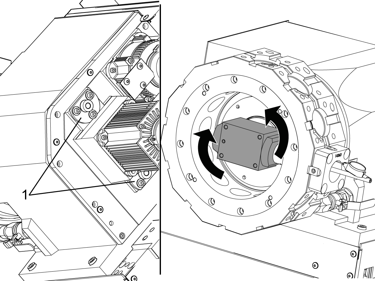
With the indicator base installed, T-0082, loosen the (6) bolts on the top and bottom alignment bushings [1].

Rotate the drive until the total indicated runout (T.I.R.) is less than .002".

Tighten the (6) bolts on the top and bottom alignment bushings [1] to lock the drive in position.

Verify the T.I.R. remains less than .002".

Remove the T-0080 and T-0082 alignment block and indicator base.

3

Insert the T-0083 output shaft alignment tool into the pocket.

Check the drive dog alignment with the tool in the vertical position.

For Classic Haas Control: Adjust parameter 487 TT Tool Change Offset to correct the alignment.

  • Press [ALARMS] key, type "DEBUG" and press [ENTER] to enter debug mode.
  • Switch to the position screen.
  • Press [F4] to activate the raw data box.
  • Highlight the "VAR" tab and press [ENTER].
  • Highlight the "AXES" tab and press [ENTER].
  • Flip the sign (if negative, make positive; if positive, make negative) on the TT-axis "PRIME ENC" position value and enter this value into PAR 487.
  • Press [ZERO RETURN], then [ALL].
  • Reinsert tool T-0065 into the vertical slots on the turret to verify that the output shaft is properly aligned.

For Next Generation Control: Go to parameter 10.082 LT_AXIS SPINDL ORIENT OFSET, type LT and press [F3] to set the live tooling orient.

Verification

Clamp, unclamp, and rotate the turret to verify that the machine is running correctly. 

Repeat any necessary steps of the procedure if error occurs. 

Recently Viewed Items

You Have No Recently Viewed Items Yet

Feedback
Haas Logo

Haas Delivered Price

This price includes shipping cost, export and import duties, insurance, and any other expenses incurred during shipping to a location in France agreed with you as a buyer. No other mandatory costs can be added to the delivery of a Haas CNC Product.

KEEP UP WITH THE LATEST HAAS TIPS AND TECHNOLOGY...

Sign up now!   

HAAS TOOLING ACCEPTS THE FOLLOWING:

  • Service & Support
  • Owners
  • Request Service
  • Operator Manuals
  • Haas Parts
  • Rotary Repair Request
  • Pre-Install Guides
  • Shopping Tools
  • Build & Price a New Haas
  • Available Inventory
  • The Haas Price List
  • CNCA Financing
  • About Haas
  • Accessibility Statement
  • DNSH Statement
  • Export Compliance
  • Careers
  • Certifications & Safety
  • Contact Us
  • History
  • Terms & Conditions
  • Haas Tooling Terms & Conditions
  • Privacy
  • Warranty
  • Haas Community
  • Haas Certification Program
  • Haas Motorsports
  • Gene Haas Foundation
  • Haas Technical Education Community
  • Events
  • Join the Conversation
  • Facebook
  • X
  • Flickr
  • YouTube
  • LinkedIn
  • Instagram
  • TikTok
© 2026 Haas Automation, Inc – CNC Machine Tools
This site is protected by reCAPTCHA and the Google Privacy Policy and Terms of Service apply.

2800 Sturgis Rd., Oxnard, CA 93030
Toll Free: (888) 817-4446 / Fax: 805-278-8554