My Haas Welcome,
!
Haas Tooling MyHaas/HaasConnect Sign In Register Haas Tooling MyHaas/HaasConnect Sign Out Welcome, My Machines Latest Activity My Quotes My Account My Users Sign Out
Find Your Distributor
  1. Select Language
    1. English
    2. Deutsch
    3. Español - ES
    4. Español - MX
    5. Français
    6. Italiano
    7. Português
    8. Český
    9. Dansk
    10. Nederlands
    11. Magyar
    12. Polski
    13. Svenska
    14. Türkçe
    15. 中文
    16. Suomi
    17. Norsk
    18. الإنجليزية
    19. български
    20. Hrvatski
    21. Ελληνικά
    22. Română
    23. Slovenský
    24. Slovenščina
    25. 한국어
    26. 日本語
    27. Українська
  • machines Main Menu
    • Vertical Mills
      Vertical Mills
      Vertical Mills View All
      • Vertical Mills
      • VF Series
      • Universal Machines
      • VR Series
      • VP-5 Prismatic
      • Pallet-Changing VMCs
      • Mini Mills
      • Mold Machines
      • High-Speed Drill Centers
      • Drill/Tap/ Mill Series
      • Toolroom Mills
      • Pocket Mill
      • Compact Mills
      • Gantry Series
      • SR Sheet Routers
      • Extra-Large VMC
      • Double-Column Mills
      • 3+2 Positioning Machines
    • Multi-Axis Solutions
      Multi-Axis Solutions
      Multi-Axis Solutions View All
      • Multi-Axis Solutions
      • Y-Axis Lathes
      • 5-Axis Mills
    • Lathes
      Lathes
      Lathes View All
      • Lathes
      • ST Series
      • Dual-Spindle
      • Box Way Series
      • Toolroom Lathes
      • Chucker Lathe
      • Pocket Lathe
      • Haas Bar Feeders
    • Horizontal Mills
      Horizontal Mills
      Horizontal Mills View All
      • Horizontal Mills
      • 50-Taper
      • 40-Taper
    • Rotaries & Indexers
      Rotaries & Indexers
      Rotaries & Indexers View All
      • Rotaries & Indexers
      • Rotary Tables
      • Indexers
      • 5-Axis Rotaries
      • Extra-Large Rotaries
    • Special Series
      Special Series
      Special Series View All
      • Special Series
      • EU_Series_Redirect
    • Automation Systems
      Automation Systems
      Automation Systems View All
      • Automation Systems
      • Mill Automation
      • Lathe Automation
      • Automatic Parts Loaders
      • Automation Models
    • Desktop Machines
      Desktop Machines
      Desktop Machines View All
      • Desktop Machines
      • Desktop Mill
      • Desktop Lathe
      • Control Simulator, Standard
      • Control Simulator, Premium
    • Shop Equipment
      Shop Equipment
      Shop Equipment View All
      • Shop Equipment
      • Knee Mill
      • Haas Manual Lathes
      • Haas Saws
    • Fabrication Machines
      Fabrication Machines
      Fabrication Machines View All
      • Fabrication Machines
      • Laser Cutting Machines
      • CNC Press Brakes
    • QUICK LINKS Special Series  Special Series 
      EU SERIES EU SERIES BUILD & PRICE | PRICE LIST BUILD & PRICE | PRICE LIST In-Stock Machines In-Stock Machines WHAT’S NEW WHAT’S NEW YOUR FIRST CNC YOUR FIRST CNC
      SHOPPING TOOLS
      • Build & Price a Haas
      • Price List
      • Available Inventory
      • CNCA Financing
      WANT TO TALK TO SOMEONE?

      A Haas Factory Outlet (HFO) can answer your questions, and walk you through your best options.

      CONTACT YOUR DISTRIBUTOR >
  • Options Main Menu
    • The Haas Control Value Option Packages
      Value Option Packages
      Value Option Packages View All
      • Value Option Packages
    • Product Image Spindles
      Spindles
      Spindles View All
      • Spindles
    • Product Image Tool Changers
      Tool Changers
      Tool Changers View All
      • Tool Changers
    • Product Image 4th- | 5th-Axis
      4th- | 5th-Axis
      4th- | 5th-Axis View All
      • 4th- | 5th-Axis
    • Product Image Turrets & Live Tooling
      Turrets & Live Tooling
      Turrets & Live Tooling View All
      • Turrets & Live Tooling
    • Product Image Probing
      Probing
      Probing View All
      • Probing
    • Haas Chip & Coolant Management Chip & Coolant Management
      Chip & Coolant Management
      Chip & Coolant Management View All
      • Chip & Coolant Management
    • The Haas Control The Haas Control
      The Haas Control
      The Haas Control View All
      • The Haas Control
    • Product Image Product Options
      Product Options
      Product Options View All
      • Product Options
    • Product Image Tooling & Fixturing
      Tooling & Fixturing
      Tooling & Fixturing View All
      • Tooling & Fixturing
    • Product Image Workholding
      Workholding
      Workholding View All
      • Workholding
    • Product Image 5-Axis Solutions
      5-Axis Solutions
      5-Axis Solutions View All
      • 5-Axis Solutions
      • 5 Easy Steps to 5-Axis
    • QUICK LINKS Special Series  Special Series 
      EU SERIES EU SERIES BUILD & PRICE | PRICE LIST BUILD & PRICE | PRICE LIST In-Stock Machines In-Stock Machines WHAT’S NEW WHAT’S NEW YOUR FIRST CNC YOUR FIRST CNC
      SHOPPING TOOLS
      • Build & Price a Haas
      • Price List
      • Available Inventory
      • CNCA Financing
      WANT TO TALK TO SOMEONE?

      A Haas Factory Outlet (HFO) can answer your questions, and walk you through your best options.

      CONTACT YOUR DISTRIBUTOR >
  • Why Haas Main Menu
      Discover the Haas Difference
    • Why Haas
    • MyHaas
    • Education Community
    • Industry 4.0
    • Haas Certification
    • Customer Testimonials
  • Service Main Menu
      Welcome to Haas Service
      SERVICE HOME Operator’s Manuals How-To Procedures Troubleshooting Guides Preventive Maintenance Haas Parts Haas Tooling Videos
  • Videos Main Menu
  • Main Menu
    • View All
    • View All
    • View All
    • View All
      • HTEC Curriculum Support
      • Haas Value Option Packages (VOP) Journey
    • View All
      • Haas 10 kg Cobot Package
      • Cobot Kits
      • DC-1 Drill Center
      • CNC Sales News
      • Do More With Your Haas
    • View All
    • View All
      • contact-us-test
      • 4 - AUTOMATION SYSTEMS
      • Carousel-V2
      • expert test
      • Demo_Day_Trident-test
      • Link Test
      • image-sale-tag-test
      • article-list-test
      • Haas 25 kg Robot Package
      • test-algolia-page
    • View All
    • View All
    • View All
    • View All
      • calc-test
    • View All
    • QUICK LINKS Special Series  Special Series 
      EU SERIES EU SERIES BUILD & PRICE | PRICE LIST BUILD & PRICE | PRICE LIST In-Stock Machines In-Stock Machines WHAT’S NEW WHAT’S NEW YOUR FIRST CNC YOUR FIRST CNC
      SHOPPING TOOLS
      • Build & Price a Haas
      • Price List
      • Available Inventory
      • CNCA Financing
      WANT TO TALK TO SOMEONE?

      A Haas Factory Outlet (HFO) can answer your questions, and walk you through your best options.

      CONTACT YOUR DISTRIBUTOR >
  • Haas Tooling Main Menu
  • Haas Service Parts Main Menu

My Haas Welcome,
!
Haas Tooling MyHaas/HaasConnect Sign In Register Haas Tooling MyHaas/HaasConnect Sign Out Welcome, My Machines Latest Activity My Quotes My Account My Users Sign Out
Find Your Distributor
  1. Select Language
    1. English
    2. Deutsch
    3. Español - ES
    4. Español - MX
    5. Français
    6. Italiano
    7. Português
    8. Český
    9. Dansk
    10. Nederlands
    11. Magyar
    12. Polski
    13. Svenska
    14. Türkçe
    15. 中文
    16. Suomi
    17. Norsk
    18. الإنجليزية
    19. български
    20. Hrvatski
    21. Ελληνικά
    22. Română
    23. Slovenský
    24. Slovenščina
    25. 한국어
    26. 日本語
    27. Українська
×

Search Results

Web Pages

Images

    • <
    • 1
    • >

Lathe Chatter - Troubleshooting - TG0092

Service Home Lathe Chatter - Troubleshooting - TG0092

Lathe Chatter - Troubleshooting - TG0092

- Jump to Cause - 1. Excessive Tool Wear 2. Excessive Tool Stick Out 3. Chip Load too Light 4. The Tool is Not On the Spindle Centerline 5. The Tool Insert is Improper for the Workpiece Material 6. The Workpiece Moves in the Chuck 7. Insufficient Support on the Workpiece 8. Worn or Damaged Live Center 9. The Center-Drilled Hole is Incorrect or Damaged 10. Coolant Issues 11. Inadequate Foundation 12. Threading - Incorrect A or P Value with G76 13. Threading - Tool Selection 14. Threading - Settings 86 and 99 Have Incorrect Values 15. Threading - Tool is Too Long 16. Threading - Machine is Not Level 17. Surface Finish Shows Chatter With Tailstock Use 18. Surface Finish Step 19. ST-40 and Above only (Machines Built after Jan 2022) Back to Top
Recently Updated Last updated: 11/13/2025

Lathe Chatter - Troubleshooting


TG0092

Excessive Tool Wear

If your tool has excessive wear, the cutting forces generated by the cut will increase. These increased cutting forces can lead to chatter during the cut. 

Inspect your tool and replace it if necessary. 

It is normal for tools to wear over time. In a stable machining process the tool wear is predictable. This will allow you to use the Tool Life Management systems that come standard in your Haas control. The tool life information can be input in to the Haas control to alert the operator to replace the tool before it negatively affects your machining process.

Refer to the Tool Life Management section for details on how to use these systems.

Excessive Tool Stick Out

Longer tools are less stiff, and thus less stable, but even small changes to tool length can make a large difference: a 10% reduction in the length-to-width ratio results in up to a 25% increase in tool stiffness.

If you must use a longer stick tool for clearance, consider using a Haas Twin Turn or Extended Twin Turn BOT holder to fully support the stick tool.

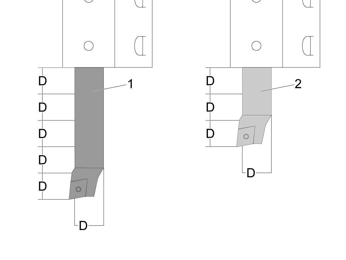
For boring bars, the material type of the bar will affect its stability. A steel boring bar (2) is stable up to a stick-out of 3 times the diameter. A carbide boring bar (1) is stable at a length up to 5 times its diameter. If you must exceed these limits, you must compromise your cut parameters to compensate for the reduced stability—reduce the depth-of-cut, feedrate, or spindle speed to compensate.

 Note: Special vibration-dampening boring bars are available when you need an extreme length-to-diameter ratio to machine a bore.

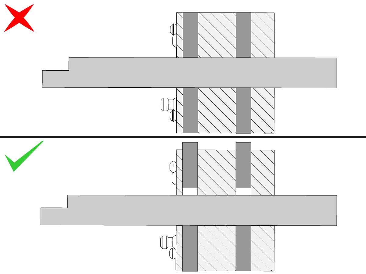
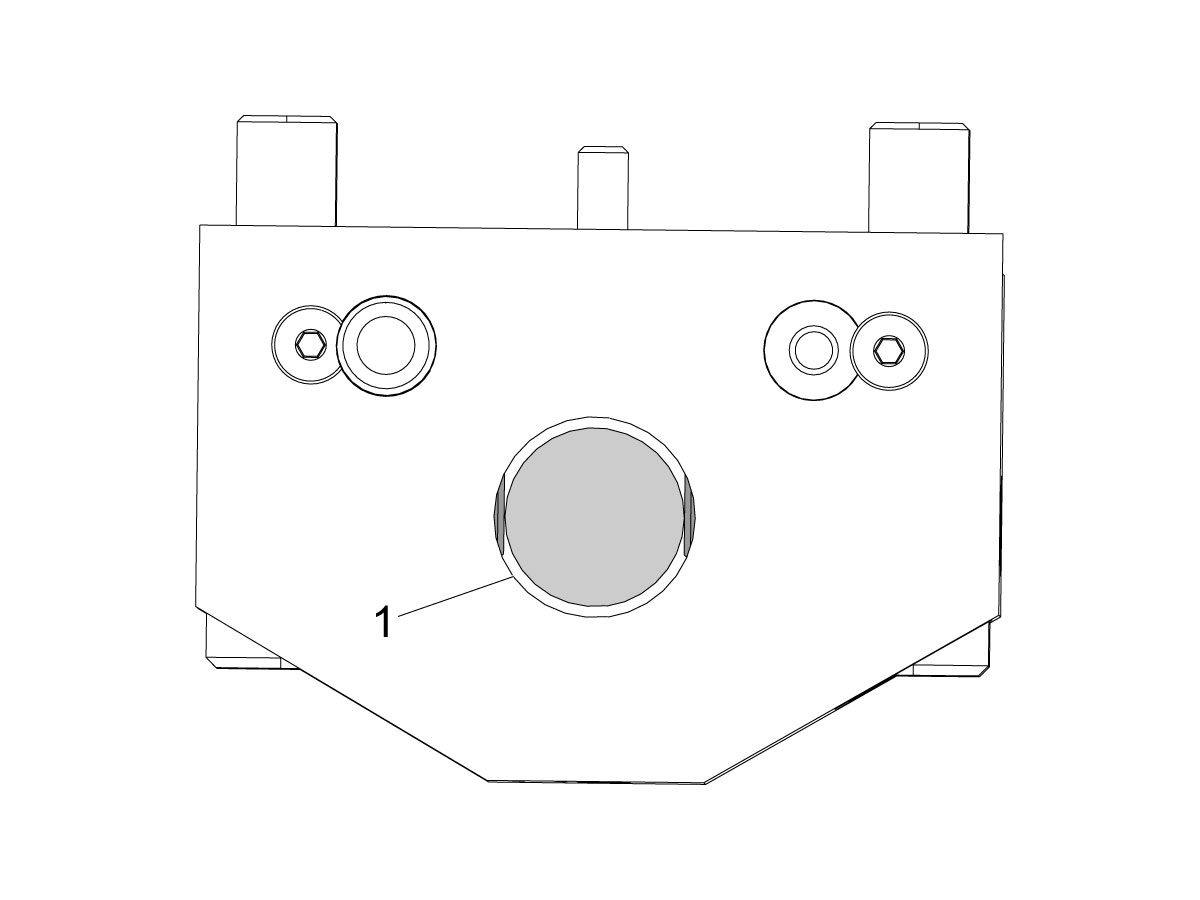
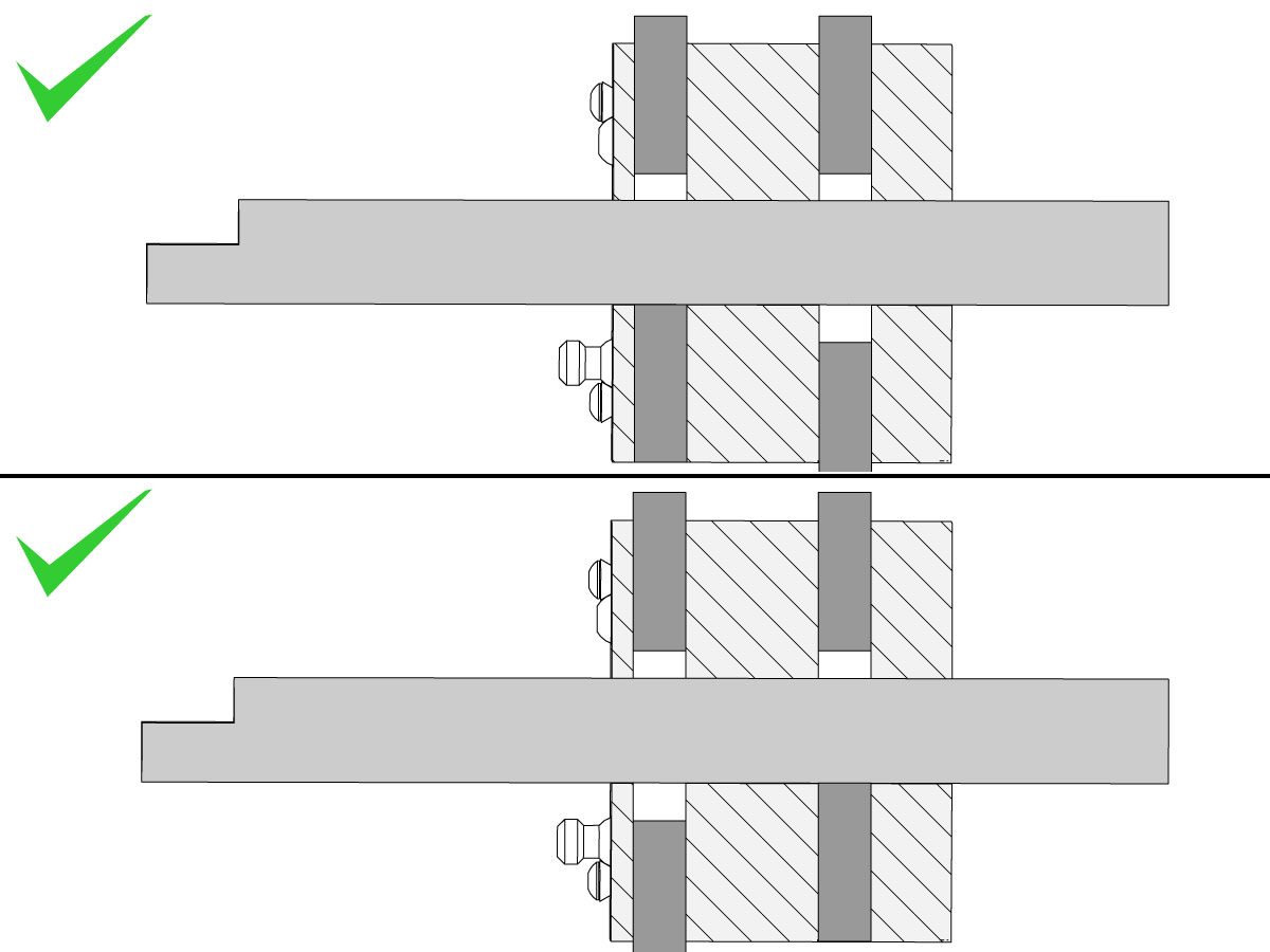
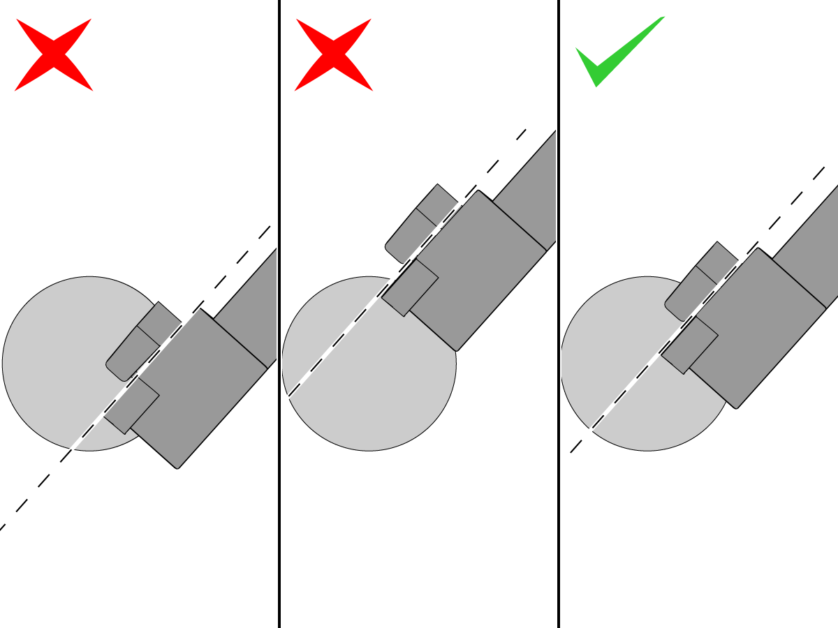
The set screws holding the bar in the holder can change the boring bar's resonant frequency. BOT holders have four set screws; two on each side. Best practice is to tighten the set screws on only one side of the holder. This ensures that the bar is held firmly against the BOT holder's bore. If you tighten the screws on both sides of the holder, then the bar may not be in contact with the bore, effectively floating in the center of the holder [1].


If you still have chatter issues using two screws on one side, you can loosen one of the set screws to change the bar's resonant frequency.

Chip Load too Light

When the cutting speed (surface feet per min or meters per min) is too high or the feedrate (feed per revolution) is too low, the cut can become unstable and begin to resonate, leaving a chattered surface finish.

Reduce the cutting speed or increase the feed rate to stabilize the cut. Refer to the tooling manufacturer's instructions for guidance as to the best speeds and feeds to use for the tooling and workpiece material. Test-run your application and use spindle speed and feed overrides to find a speed/feed combination that does not chatter.

 Note: Check the tool insert box for cut parameter recommendations. Many manufacturers print the cut information directly on the insert box label.

 Note: If you are still experiencing high runout and poor surface finish problems after troubleshooting, see the Spindle - Lathe Troubleshooting Guide.

The Tool is Not On the Spindle Centerline

If the cutting edge of your tool is not on the spindle centerline, excessive cutting forces can cause chatter, accuracy, and tool life issues.

Corrective Action:

Make sure that the stick tools are the correct size for your turret or tool holder.

Make sure that the seat under the insert is the correct thickness.

On Y-axis lathes, you can use a Y-axis tool offset to bring the cutting edge to the spindle centerline.

Inspect and correct any alignment errors in your machine tool.

The Tool Insert is Improper for the Workpiece Material

Insert selection is critical for a stable cut. The chip-breakers, coatings, radius sizes, geometry, and carbide grade must be designed for the workpiece material. Improper inserts can cause problems with surface finish, tool life, and chatter

Corrective Action:

Consult with your cutting tool vendor to select the proper insert geometry, radius size, coating and carbide grade for you application.

The Workpiece Moves in the Chuck

If your workpiece moves in the workholding during  the cut, you will have accuracy issues, difficulty holding tolerances and chatter issues.

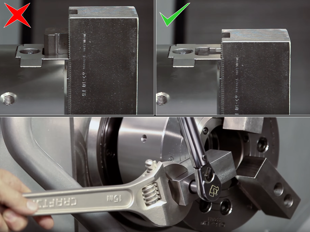
Incorrectly bored chuck jaws can let the workpiece move. The soft jaws should be machined to match the nominal size of the part being held. 

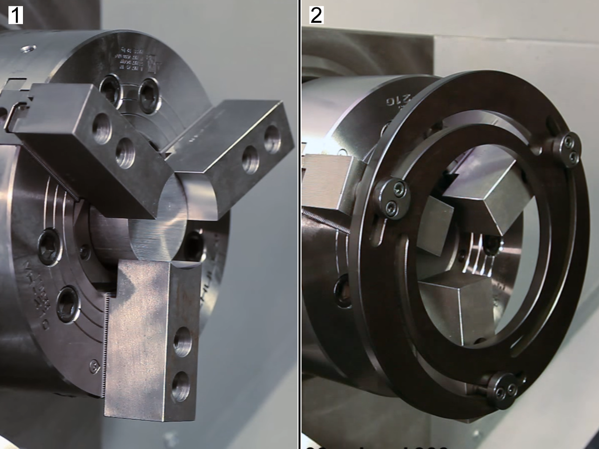
Be sure to use a chuck jaw support slug (1) or adjustable boring ring (2) in the center travel of the jaws, before you machine the jaws. If the Jaws are too close to the top of the stroke you will have diffucalty loading and unloading your workpiece in the jaws, if the jaws are too close to the bottom of the stroke the full clamping force will not achieved.   

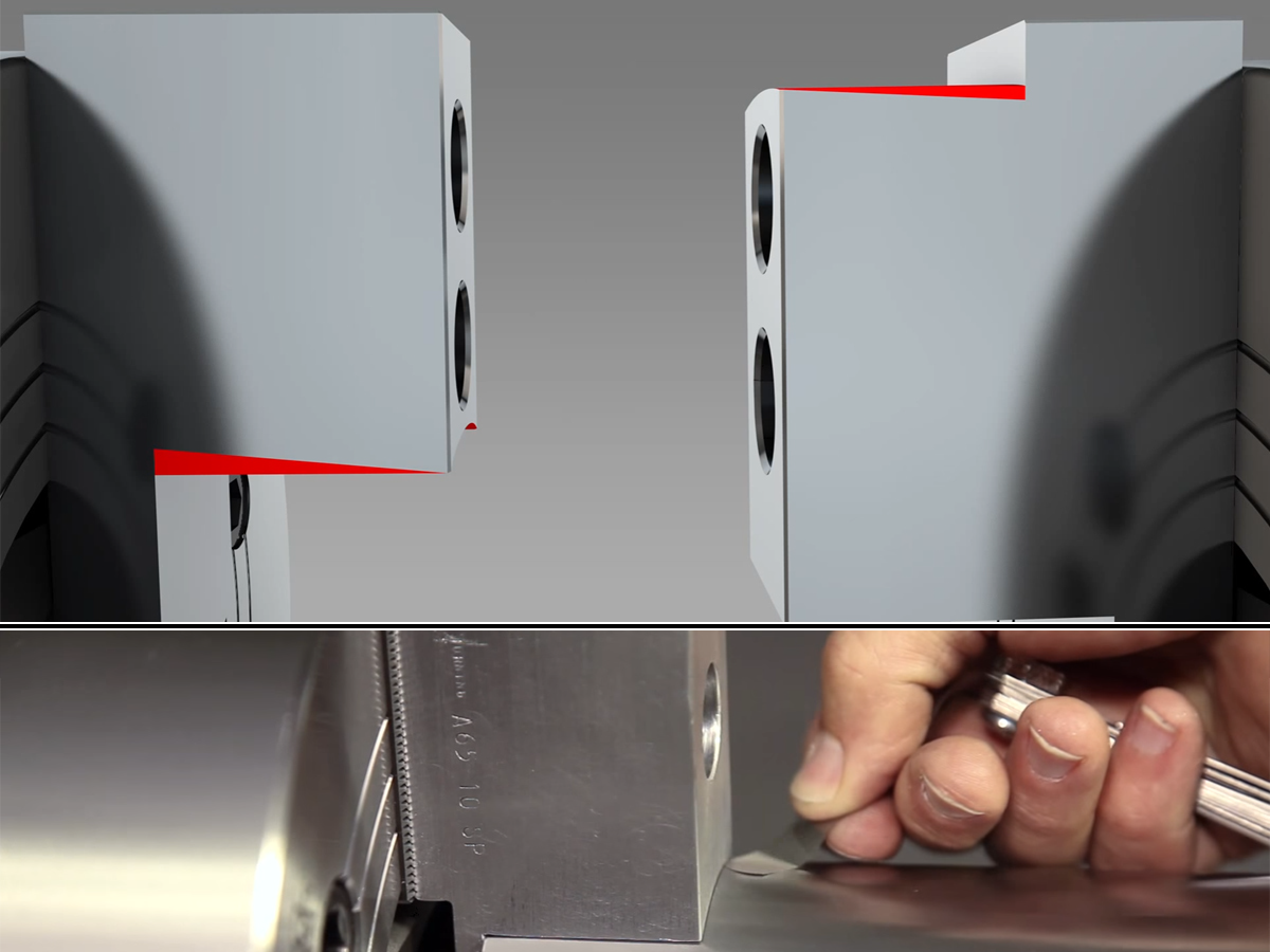
Use a 0.001" (0.03 mm) feeler gauge to check for gaps between the workpiece and the chuck jaws. Check both the front and the back. The jaws may have deflected from the clamp force, in some cases you may need to machine a slight taper in the jaws to compensate for the jaw's deflection allowing for full jaw contact with the workpeice. 

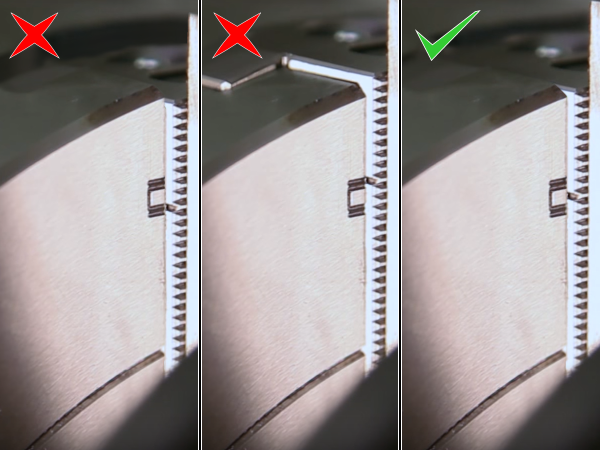
Make sure that the chuck jaws are tight, and that the screws do not bottom out on the T-nuts or T-slot. The T-nuts should not extend outside the T-slots.

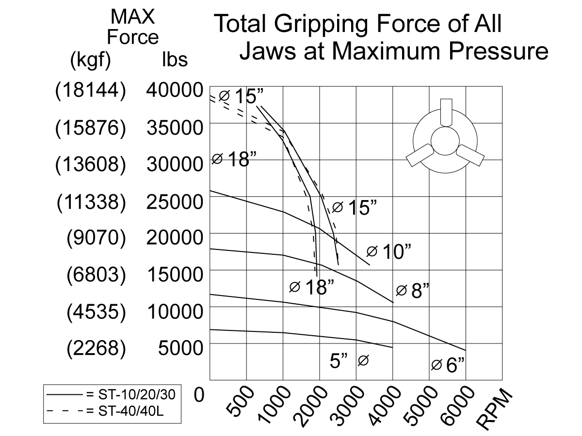
When OD clamping parts, the centrifugal forces generated at high RPMs will reduce the clamp force and may allow the part to move. Use this chart to determine the if you need to increase the clamp force on the chuck or reduce the max RPM during your program. You can find this chart on a sticker near the hydraulically pump on your lathe.

Refer to:

  • How to Properly Cut Lathe Soft Jaws — Part 1: Fundamentals and OD Gripping
  • How to Properly Cut Lathe Soft Jaws — Part 2: ID Gripping, Re-cutting, and Adding a Taper

 Note: Be sure to clean and deburr you workpiece before you clamp it into your workholding device. A dirty surface, chips, or burrs can let the workpiece move during the cut.

Insufficient Support on the Workpiece

If the workpiece is not properly supported, it will begin to vibrate and introduce chatter into the cut. 

As a general rule, if the portion of the workpiece that extends past the chuck exceeds a diameter-to-length ratio of 3:1, use a tailstock to stabilize the cut. 

If the length-to-diameter ratio of your workpiece exceeds 10:1, you may need to use the additional support of a steady rest, different workholding, or a different machining strategy to stabilize the cut.

Helpful Hint:
Consider using the Spindle Speed Variation (SSV) feature to disrupt chatter.

For more details on tailstocks watch Tailstock Fundamentals: How to use the Tailstock on a Haas Lathe.

Worn or Damaged Live Center

A worn or damaged live center can introduce vibrations and let the part move. This can cause chatter, taper, poor surface finish, and tool life issues.

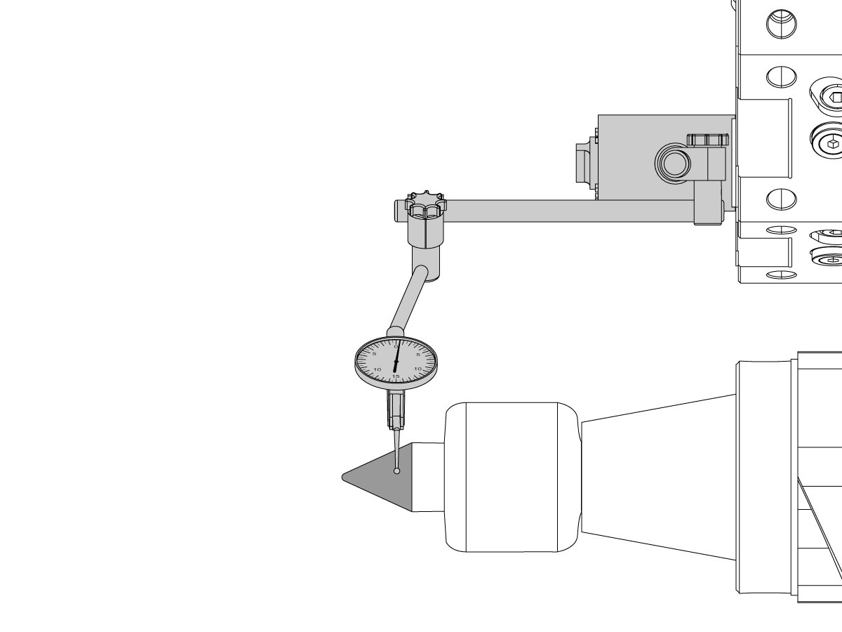
Inspect live centers for excessive runout and damaged bearings while they’re still in the machine.

Check runout by placing an indicator on the 60 degree point, then gently rotate the center's point. The TIR should be within the manufacturer’s specification.

Check for bearing wear by gripping the point firmly and rotating it in one direction. The spindle should turn freely, if you can feel hesitations or roughness this indicates bearing wear.

 Note: Live centers have a service life and a maintenance schedule. Refer to the live center manufacturer's documentation for details on your live center. Excessive tailstock pressure can prematurely wear out your live center.

The Center-Drilled Hole is Incorrect or Damaged

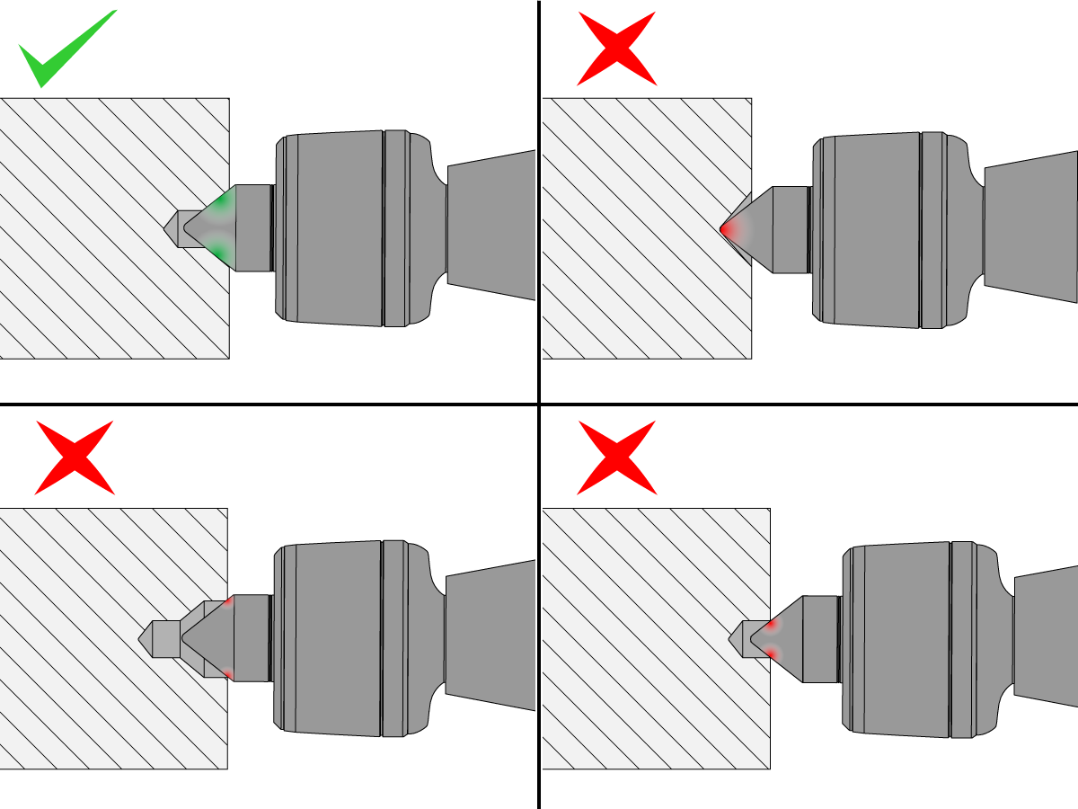
If the center-drilled hole has the wrong angle, is too small, too shallow, too deep, or is damaged, the live center will not have sufficient contact with the workpiece to properly stabilize the cut.

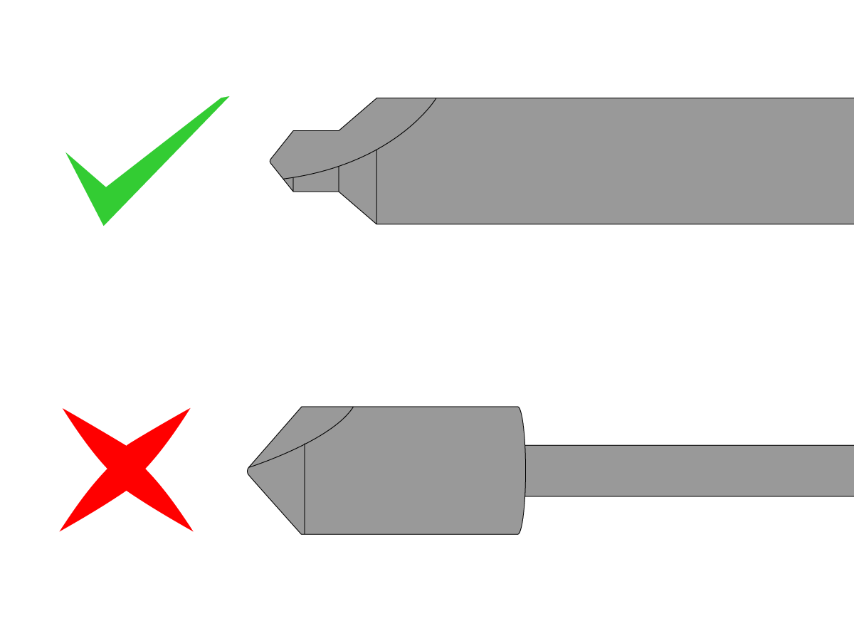
Be sure to use a 60° center drill tool. Countersink tools do not have the tip relief required for the live center.

Inspect the center-drilled hole. If necessary, machine it again.

For more details center-drill requirements watch this video on Tailstock Fundamentals.

Coolant Issues

Incorrectly aimed coolant nozzles or obstructions in the stream can prevent coolant from reaching the cutting area. Adjust your coolant nozzles to deliver coolant to the cutting area.

Be sure to use the recommended coolant mixture concentration in your applications. If your concentration is too lean, the reduced lubricity can negatively affect your tool life and surface finish.
There are many different coolants for different applications and materials. Contact your coolant dealer for advice.

Inadequate Foundation

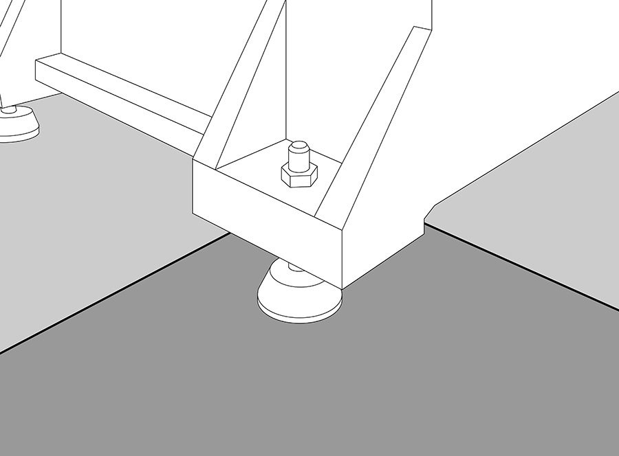
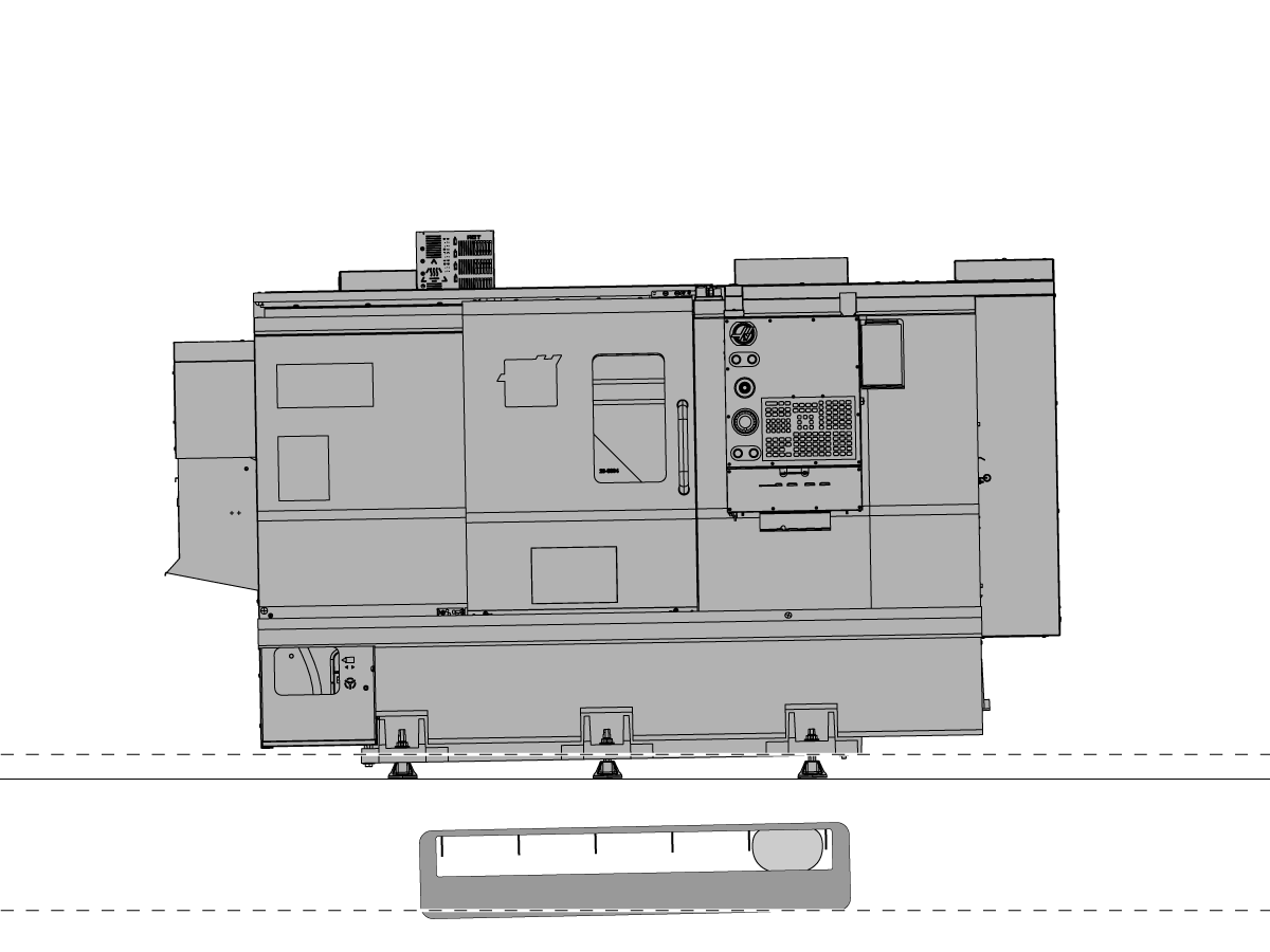
The machine must sit on a solid and stable foundation. Refer to Pre-Installation Information for a full description of the foundation requirements.

If the foundation is badly cracked, move the machine to a location with a solid foundation, or repair the foundation.

The machine should sit on one continuous slab of reinforced concrete. If the machine straddles more than one slab, you may need to move the machine to a single, continuous slab.

Threading - Incorrect A or P Value with G76

Use the optional A and P codes with a G76 threading cycle to control the infeed angle (A) and cutting method (P). 

The A value specifies the infeed angle, or the tool nose angle, for the thread. This value can range from 0 to 120 degrees; do not use a decimal point. If you do not specify an A value, the control assumes zero.

The P value specifies the cutting method. The options are P1, P2, P3 and P4. These control whether the depth of cut is a constant depth with each pass, or a constant cutting amount that reduces the depth of cut the deeper into the thread it goes. The P value also specifies single edge or double edge cutting. If you do not specify a P code, the control selects the P code designated in Setting 232.

  • P1 Single edge cutting, cutting amount constant
  • P2 Double edge cutting, cutting amount constant
  • P3 Single edge cutting, cutting depth constant
  • P4 Double edge cutting, cutting depth constant 

Helpful Hint:

To reduce chatter while threading, use an A value 1-3 degrees less than the included angle of the thread; for example, use an A57, A58 or A59 to cut a 60-degree included angle thread. This allows for clearance on the back side of the insert so it does not contact the thread form until the final depth cut. 

Refer to G76 Threading Cycle, Multiple Pass (Group 00) - Lathe for more details on threading.

Threading - Tool Selection

The insert geometry, insert grade and/or insert shim are incorrect for the application.

Corrective Action:

Consult with your tooling manufacturer for recommendations on proper tool selection for your application, and make adjustments where necessary.

Helpful Hint 1:

Threading inserts come in many different shapes and sizes. Topping inserts are the most common threading inserts used on a CNC machine. Topping inserts cut one full thread form at a time, and they are designed for a specific pitch.

Be sure to use the correct insert for your application.

Helpful Hint 2:

Check under the insert for a seat, sometimes referred to as a shim. This seat is ground to an angle. Different thread diameters require different seat angles. Check with the insert manufacturer to be sure that you are using the correct seat for the thread being cut.

Threading - Settings 86 and 99 Have Incorrect Values

Setting 99 (THREAD MIN CUT) and setting 86 (THREAD FINISH ALLOWANCE) control the minimum roughing depth-of-cut and the final finish pass depth-of-cut for a G76 threading cycle.

Corrective action:

Use an infeed chart from the tooling manufacturer to set the values for Setting 86 and 99.

This chart specifies the minimum and final cut values for a specific thread size, as well as the total number of depth cuts for roughing.

Threading - Tool is Too Long

The OD or ID threading tool is too long, or it is not properly supported.

Corrective Action:

Adjust the OD stick tool holder so that the tool holder’s projection length from the turret is as short as possible. If you must use a longer stick tool for clearance, consider using a Haas Twin Turn or Extended Twin Turn BOT holder to fully support the stick tool. You can get these holders on parts.haascnc.com.

Adjust the ID boring bar holder so that the tool’s projection length from the tool older is as short as possible. The material type of the bar will affect its stability. A steel boring bar is stable up to a stick-out of 3 times the diameter. A carbide boring bar is stable at a length up to 5 times its diameter. If you must exceed these limits, you must compromise your cut parameters to compensate for the reduced stability—reduce the depth-of-cut, or spindle speed to compensate.

Helpful Hints:

If you need to use a bushing for the boring bar, use a split bushing to increase bar support.

Special vibration-dampening boring bars are available when you need an extreme length-to-diameter ratio to machine an ID thread.

Threading - Machine is Not Level

To operate correctly, the machine must be level. An out-of-level machine can have problems such as poor surface finish, tapered parts, accuracy and repeatability issues, out-of-round circular motion, and out-of-true linear motion.

Watch the Lathe Leveling video to learn how to properly level your Haas lathe, or contact your Haas Factory Outlet to have your machine’s level checked.

Surface Finish Shows Chatter With Tailstock Use

A linear guide, the ball screw, or the ball nut is damaged:

Before removing the waycovers, make sure these items on the machine are within specification. If they are not, make adjustments and test the machine.

  1. Machine Level
  2. Alignment of the Spindle
  3. Alignment of the Turret
  4. Alignment of the Tailstock

If the problem continues, remove the way covers and examine the linear guides, the ball screw, and the ball nut for damage, movement, or signs of a crash.

 Note: Damaged or loose bearings in the trucks for the linear guides can cause the machine to chatter during aggressive cutting. The linear guide pads on the machine should not have any side to side / up and down movement over 0.002".

If the linear guides, the ball screw, or the ball nut are damaged or loose, replace them.

The quill has play inside the tailstock body. (ST-20/30):

If the quill has play, replace the complete quill assembly. The assembly is not field serviceable.

Install a zero-clearance linear guide pad. (SL-30/SL-30T/TL-25):

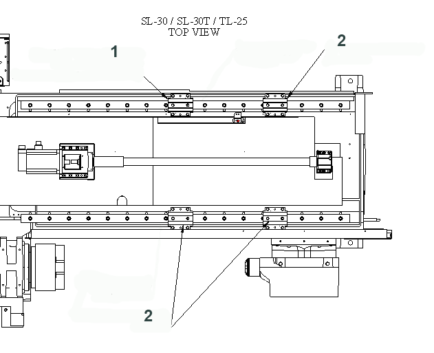
If an SL-30/SL-30T/TL-25 has chatter/vibration during tailstock/secondary spindle use, determine if the z-axis linear guides are Rexroth guides. If they are, replace the existing left rear linear guide pad with a zero-clearance linear guide pad (P/N 93-1320).  If the machine still has chatter, replace the second rear pad with another zero-clearance linear guide pad.

  1. Zero Clerance linear guide pad
  2. Regular linear guide pads.

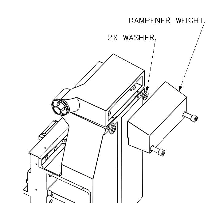
Add a tailstock dampener weight. (SL-20/30):

A dampener weight and a good quality live center can solve tailstock chatter issues in SL-20 and SL-30 lathes. Order the necessary parts as shown below:

SL-20
Dampener Weight, P/N 20-3041 QTY: 1
Washer,    P/N 45-2011 QTY: 2
SHCS 5/8-11 X 4”,  P/N 40-0002 QTY: 2

SL-30
Dampener Weight, P/N 20-3042 QTY: 1
Washer,    P/N 45-2011 QTY: 2
SHCS 5/8-11 X 4”,  P/N 40-0002 QTY: 2

Refer to: Lathe - Hydraulic Tailstock - Troubleshooting Guide

Surface Finish Step

ST-40 and Above only (Machines Built after Jan 2022)

During long cuts along the Z-axis after rapid movement on the X-axis if a surface finish step is observed verify that parameter 1.042 is set to 0.

 Note: These steps are very small (0.0002" - 0.0003") but visible.

Recently Viewed Items

You Have No Recently Viewed Items Yet

Feedback
Haas Logo

Haas Delivered Price

This price includes shipping cost, export and import duties, insurance, and any other expenses incurred during shipping to a location in France agreed with you as a buyer. No other mandatory costs can be added to the delivery of a Haas CNC Product.

KEEP UP WITH THE LATEST HAAS TIPS AND TECHNOLOGY...

Sign up now!   

HAAS TOOLING ACCEPTS THE FOLLOWING:

  • Service & Support
  • Owners
  • Request Service
  • Operator Manuals
  • Haas Parts
  • Rotary Repair Request
  • Pre-Install Guides
  • Shopping Tools
  • Build & Price a New Haas
  • Available Inventory
  • The Haas Price List
  • CNCA Financing
  • About Haas
  • Accessibility Statement
  • DNSH Statement
  • Export Compliance
  • Careers
  • Certifications & Safety
  • Contact Us
  • History
  • Terms & Conditions
  • Haas Tooling Terms & Conditions
  • Privacy
  • Warranty
  • Haas Community
  • Haas Certification Program
  • Haas Motorsports
  • Gene Haas Foundation
  • Haas Technical Education Community
  • Events
  • Join the Conversation
  • Facebook
  • X
  • Flickr
  • YouTube
  • LinkedIn
  • Instagram
  • TikTok
© 2026 Haas Automation, Inc – CNC Machine Tools
This site is protected by reCAPTCHA and the Google Privacy Policy and Terms of Service apply.

2800 Sturgis Rd., Oxnard, CA 93030
Toll Free: (888) 817-4446 / Fax: 805-278-8554