My Haas Welcome,
!
Haas Tooling MyHaas/HaasConnect Sign In Register Haas Tooling MyHaas/HaasConnect Sign Out Welcome, My Machines Latest Activity My Quotes My Account My Users Sign Out
Find Your Distributor
  1. Select Language
    1. English
    2. Deutsch
    3. Español - ES
    4. Español - MX
    5. Français
    6. Italiano
    7. Português
    8. Český
    9. Dansk
    10. Nederlands
    11. Magyar
    12. Polski
    13. Svenska
    14. Türkçe
    15. 中文
    16. Suomi
    17. Norsk
    18. الإنجليزية
    19. български
    20. Hrvatski
    21. Ελληνικά
    22. Română
    23. Slovenský
    24. Slovenščina
    25. 한국어
    26. 日本語
    27. Українська
  • machines Main Menu
    • Vertical Mills
      Vertical Mills
      Vertical Mills View All
      • Vertical Mills
      • VF Series
      • Universal Machines
      • VR Series
      • VP-5 Prismatic
      • Pallet-Changing VMCs
      • Mini Mills
      • Mold Machines
      • High-Speed Drill Centers
      • Drill/Tap/ Mill Series
      • Toolroom Mills
      • Pocket Mill
      • Compact Mills
      • Gantry Series
      • SR Sheet Routers
      • Extra-Large VMC
      • Double-Column Mills
      • 3+2 Positioning Machines
    • Multi-Axis Solutions
      Multi-Axis Solutions
      Multi-Axis Solutions View All
      • Multi-Axis Solutions
      • Y-Axis Lathes
      • 5-Axis Mills
    • Lathes
      Lathes
      Lathes View All
      • Lathes
      • ST Series
      • Dual-Spindle
      • Box Way Series
      • Toolroom Lathes
      • Chucker Lathe
      • Pocket Lathe
      • Haas Bar Feeders
    • Horizontal Mills
      Horizontal Mills
      Horizontal Mills View All
      • Horizontal Mills
      • 50-Taper
      • 40-Taper
    • Rotaries & Indexers
      Rotaries & Indexers
      Rotaries & Indexers View All
      • Rotaries & Indexers
      • Rotary Tables
      • Indexers
      • 5-Axis Rotaries
      • Extra-Large Rotaries
    • Special Series
      Special Series
      Special Series View All
      • Special Series
      • EU_Series_Redirect
    • Automation Systems
      Automation Systems
      Automation Systems View All
      • Automation Systems
      • Mill Automation
      • Lathe Automation
      • Automatic Parts Loaders
      • Automation Models
    • Desktop Machines
      Desktop Machines
      Desktop Machines View All
      • Desktop Machines
      • Desktop Mill
      • Desktop Lathe
      • Control Simulator, Standard
      • Control Simulator, Premium
    • Shop Equipment
      Shop Equipment
      Shop Equipment View All
      • Shop Equipment
      • Knee Mill
      • Haas Manual Lathes
      • Haas Saws
    • Fabrication Machines
      Fabrication Machines
      Fabrication Machines View All
      • Fabrication Machines
      • Laser Cutting Machines
      • CNC Press Brakes
    • QUICK LINKS Special Series  Special Series 
      EU SERIES EU SERIES BUILD & PRICE | PRICE LIST BUILD & PRICE | PRICE LIST In-Stock Machines In-Stock Machines WHAT’S NEW WHAT’S NEW YOUR FIRST CNC YOUR FIRST CNC
      SHOPPING TOOLS
      • Build & Price a Haas
      • Price List
      • Available Inventory
      • CNCA Financing
      WANT TO TALK TO SOMEONE?

      A Haas Factory Outlet (HFO) can answer your questions, and walk you through your best options.

      CONTACT YOUR DISTRIBUTOR >
  • Options Main Menu
    • The Haas Control Value Option Packages
      Value Option Packages
      Value Option Packages View All
      • Value Option Packages
    • Product Image Spindles
      Spindles
      Spindles View All
      • Spindles
    • Product Image Tool Changers
      Tool Changers
      Tool Changers View All
      • Tool Changers
    • Product Image 4th- | 5th-Axis
      4th- | 5th-Axis
      4th- | 5th-Axis View All
      • 4th- | 5th-Axis
    • Product Image Turrets & Live Tooling
      Turrets & Live Tooling
      Turrets & Live Tooling View All
      • Turrets & Live Tooling
    • Product Image Probing
      Probing
      Probing View All
      • Probing
    • Haas Chip & Coolant Management Chip & Coolant Management
      Chip & Coolant Management
      Chip & Coolant Management View All
      • Chip & Coolant Management
    • The Haas Control The Haas Control
      The Haas Control
      The Haas Control View All
      • The Haas Control
    • Product Image Product Options
      Product Options
      Product Options View All
      • Product Options
    • Product Image Tooling & Fixturing
      Tooling & Fixturing
      Tooling & Fixturing View All
      • Tooling & Fixturing
    • Product Image Workholding
      Workholding
      Workholding View All
      • Workholding
    • Product Image 5-Axis Solutions
      5-Axis Solutions
      5-Axis Solutions View All
      • 5-Axis Solutions
      • 5 Easy Steps to 5-Axis
    • QUICK LINKS Special Series  Special Series 
      EU SERIES EU SERIES BUILD & PRICE | PRICE LIST BUILD & PRICE | PRICE LIST In-Stock Machines In-Stock Machines WHAT’S NEW WHAT’S NEW YOUR FIRST CNC YOUR FIRST CNC
      SHOPPING TOOLS
      • Build & Price a Haas
      • Price List
      • Available Inventory
      • CNCA Financing
      WANT TO TALK TO SOMEONE?

      A Haas Factory Outlet (HFO) can answer your questions, and walk you through your best options.

      CONTACT YOUR DISTRIBUTOR >
  • Why Haas Main Menu
      Discover the Haas Difference
    • Why Haas
    • MyHaas
    • Education Community
    • Industry 4.0
    • Haas Certification
    • Customer Testimonials
  • Service Main Menu
      Welcome to Haas Service
      SERVICE HOME Operator’s Manuals How-To Procedures Troubleshooting Guides Preventive Maintenance Haas Parts Haas Tooling Videos
  • Videos Main Menu
  • Main Menu
    • View All
    • View All
    • View All
    • View All
      • HTEC Curriculum Support
      • Haas Value Option Packages (VOP) Journey
    • View All
      • Haas 10 kg Cobot Package
      • Cobot Kits
      • DC-1 Drill Center
      • CNC Sales News
      • Do More With Your Haas
    • View All
    • View All
      • contact-us-test
      • 4 - AUTOMATION SYSTEMS
      • Carousel-V2
      • expert test
      • Demo_Day_Trident-test
      • Link Test
      • image-sale-tag-test
      • article-list-test
      • Haas 25 kg Robot Package
      • test-algolia-page
    • View All
    • View All
    • View All
    • View All
      • calc-test
    • View All
    • QUICK LINKS Special Series  Special Series 
      EU SERIES EU SERIES BUILD & PRICE | PRICE LIST BUILD & PRICE | PRICE LIST In-Stock Machines In-Stock Machines WHAT’S NEW WHAT’S NEW YOUR FIRST CNC YOUR FIRST CNC
      SHOPPING TOOLS
      • Build & Price a Haas
      • Price List
      • Available Inventory
      • CNCA Financing
      WANT TO TALK TO SOMEONE?

      A Haas Factory Outlet (HFO) can answer your questions, and walk you through your best options.

      CONTACT YOUR DISTRIBUTOR >
  • Haas Tooling Main Menu
  • Haas Service Parts Main Menu

My Haas Welcome,
!
Haas Tooling MyHaas/HaasConnect Sign In Register Haas Tooling MyHaas/HaasConnect Sign Out Welcome, My Machines Latest Activity My Quotes My Account My Users Sign Out
Find Your Distributor
  1. Select Language
    1. English
    2. Deutsch
    3. Español - ES
    4. Español - MX
    5. Français
    6. Italiano
    7. Português
    8. Český
    9. Dansk
    10. Nederlands
    11. Magyar
    12. Polski
    13. Svenska
    14. Türkçe
    15. 中文
    16. Suomi
    17. Norsk
    18. الإنجليزية
    19. български
    20. Hrvatski
    21. Ελληνικά
    22. Română
    23. Slovenský
    24. Slovenščina
    25. 한국어
    26. 日本語
    27. Українська
×

Search Results

Web Pages

Images

    • <
    • 1
    • >

9 - VF/VM - 40T - Spindle

VF/VM-Series - Service Manual


  • 1 - VF/VM - Introduction
  • 2 - VF/VM - Specifications
  • 3 - VF/VM - Installation
  • 4 - VF/VM - Umbrella Tool Changer
  • 5 - VF/VM - HSK - SMTC
  • 6 - VF/VM - 40T/50T - SMTC
  • 7 - VF/VM - Axis Motion
  • 8 - VF/VM - HSK - Spindle
  • 9 - VF/VM - 40T - Spindle
  • 10 - VF/VM - 40T - Spindle Motor
  • 11 - VF/VM - 40T - Gearbox
  • 12 - VF/VM - 50T - Spindle
  • 13 - VF/VM - 50T - Gearbox
  • 14 - VF/VM - Lubrication Systems
  • 15 - VF/VM - Electrical Control
  • 16 - VF/VM - Chip Removal and Coolant
  • 17 - VF/VM - Workholding
  • 18 - VF/VM - Maintenance
  • 19 - VF/VM - Autodoor
  • 20 - VF/VM - Robot and Automation
  • 21 - VF/VM - Enclosure
  • 22 - VF/VM - CAN Bus Systems
  • 23 - VF/VM - Spindle C-Axis Drive

Go To :

  • 9.1 40T - Inline Pin Drive Spindle - Replacement
  • 9.2 40T - Inline Spider Coupling Spindle - Replacement
  • 9.3 40T - Spindle - Troubleshooting
  • 9.4 40T - Spindle Drawbar - Troubleshooting

9.1 40T - Inline Pin Drive Spindle - Replacement

Recently Updated

VMC - 40-Taper - Inline Pin-Drive Spindle - Replacement


AD0318

Revision B - 12/2025

Introduction

The following service video shows how to replace a 40T Inline Spindle.

  NOTE:  This  service video is for reference only and does not replace the written procedure. 

This procedure tells you how to replace a VMC - 40-Taper Inline Pin-Drive Spindle. For a DT/DM machine, refer to the DT/DM - Pin Drive - Spindle - Replacement - AD0650 procedure.

This Document Applies to the Following Service Kits:

  • 93-30-11972C SPINDLE, SVC, 40T INLINE 15K PIN DRIVE
  • 93-30-11972D SPINDLE 40T INLINE 15K PIN DRIVE SVC
  • 93-30-12298A SPINDLE 40T INLINE 8/10K PIN W/DB GREASE
  • 93-30-12298B SPINDLE 40T INLINE 8/10K PIN W/DB GREASE
  • 93-30-12504A SPINDLE 40T 8/10/12K VMC INLIN PIN SVC
  • 93-30-12504B SPINDLE 40T INLINE 8/10/12K PIN DRIVE SVC
  • 93-30-13432 SPINDLE 40T 8/10/12K VMC INLIN PIN SVC
  • 93-30-13432A SPINDLE 40T 8/10/12K PIN DRV SVC 
  • 93-30-13455 SPINDLE 40T 15K VMC INCLINE PIN SVC
  • 93-30-14228 SPINDLE 40T INLINE 15K PIN DRV W/DB SVC
  • 93-30-13749 SPINDLE 40T INLINE 8/10K PIN W/DB GREASE
  • 93-30-14456 SPINDLE 40T INLIN 18K PIN DRIVE W/DB SVC

 Note: If you install the same spindle that you remove or a new spindle, record the location of the spindle shims. Install the spindle shims in the same location and then do the VMC - Spindle - Spindle Sweep procedure.

Machine Compatibility

Do this procedure on vertical mills that have a 40-taper inline pin-drive made after May, 2016

Spindle Removal

1

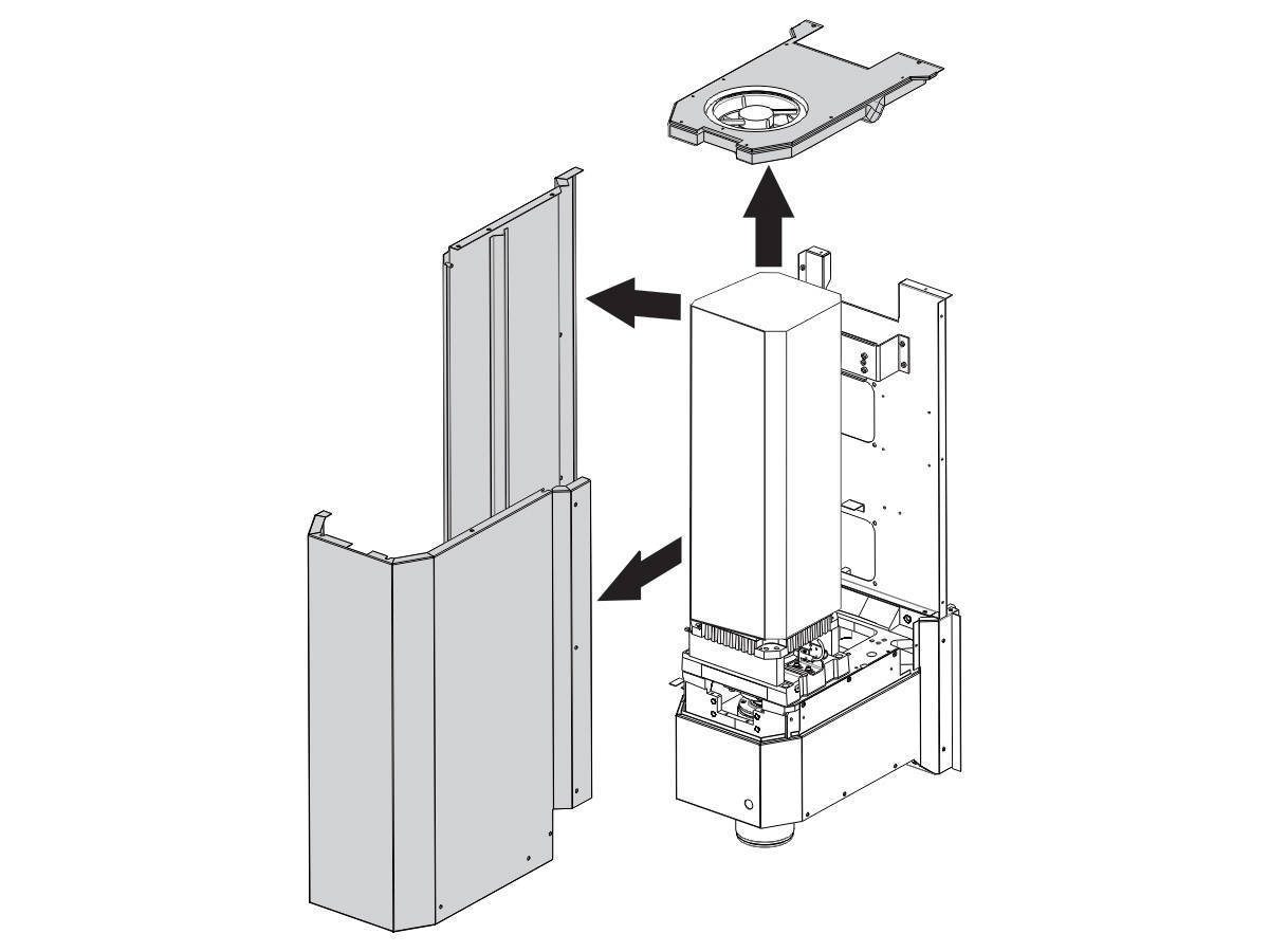
Remove the spindle head cover panels. 

2

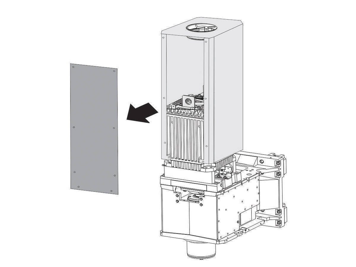
Remove the front motor shroud panel.

3

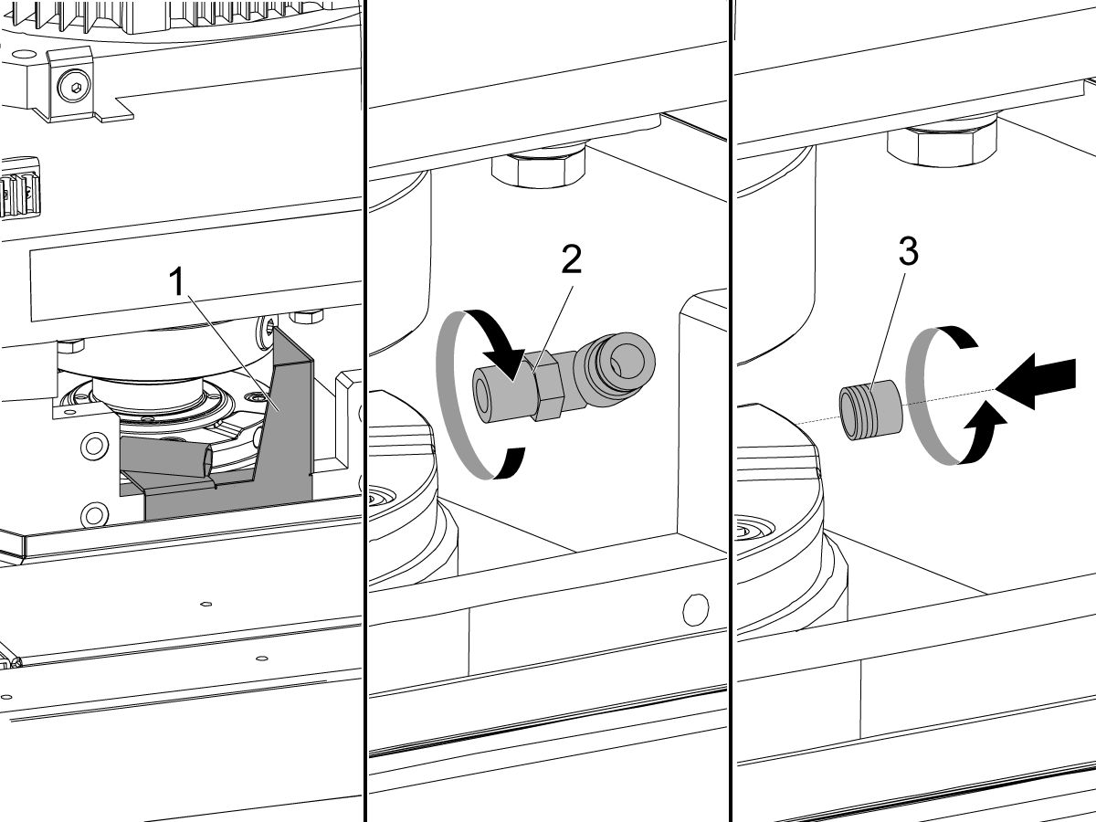
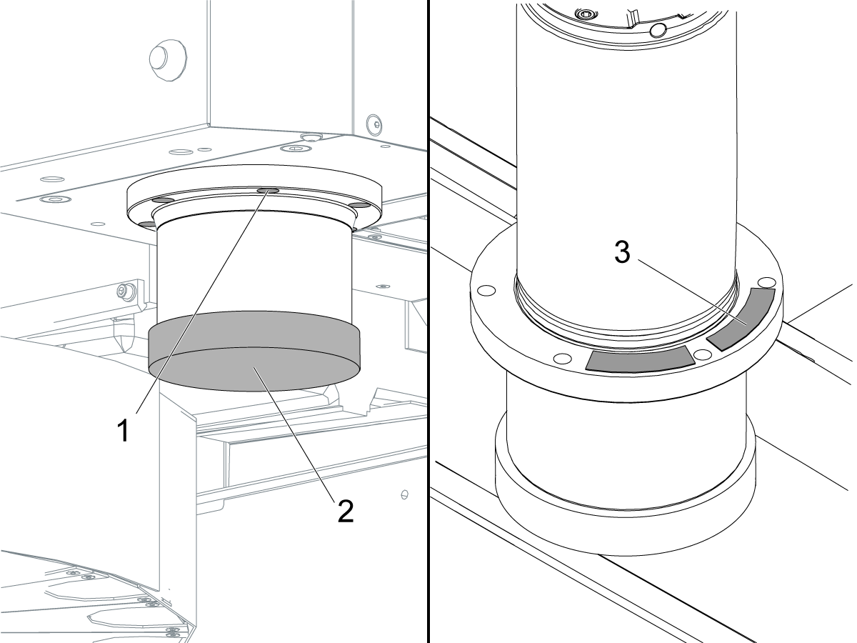
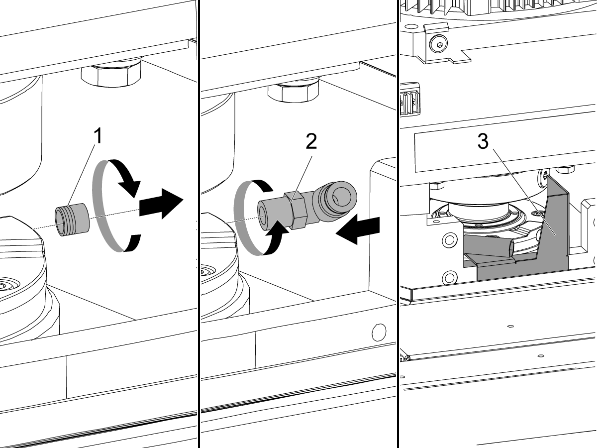
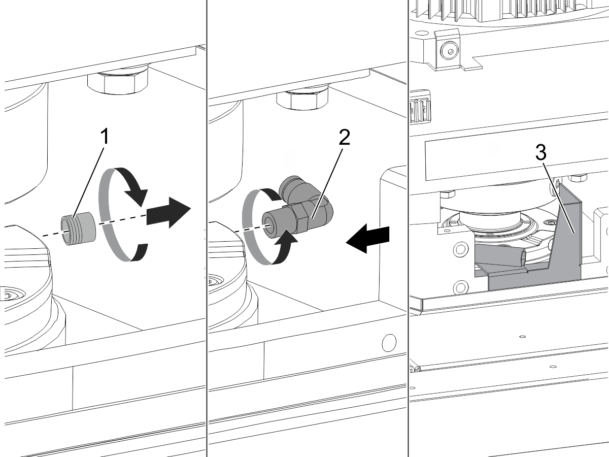
Remove the front air scraper [1].

Disconnect the spindle lubrication tube.

Remove the 90° spindle lubrication fitting [2].

Install a 1/8" NPT plug [3] into the lubrication port. Install the plug [3] flush or below flush with the surface of the spindle.

4

Put an oil pan on the table to catch all oil leaks.

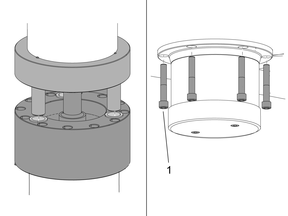
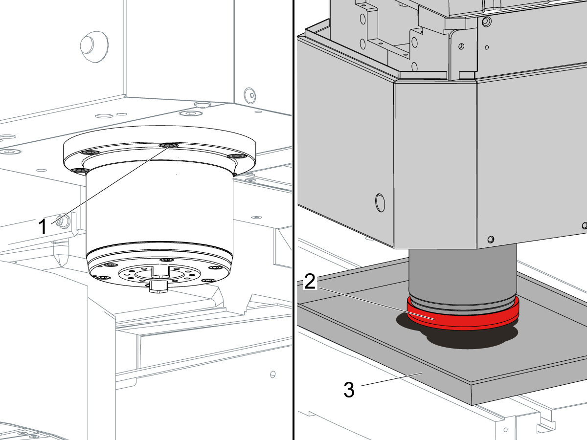
Loosen the (6) spindle screws [1] approximately (2) turns.

Install the protective cap [2] over the spindle nose.

 Caution: The protective cap is necessary. It prevents damage to the spindle when it touches the table in the next step.

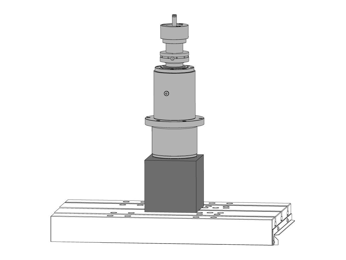
Jog the Z Axis in the negative (-) direction until the spindle touches the table. If the spindle does not touch the table, put a wooden or aluminum block under the spindle.

Remove the (6) spindle screws [1].

Jog the Z Axis in the positive (+) direction until the spindle is fully out of the spindle head and be removed. 

Remove the shims [3].

Spindle Installation Preparation

1

Jog the Z Axis in the positive (+) direction to the top of travel.

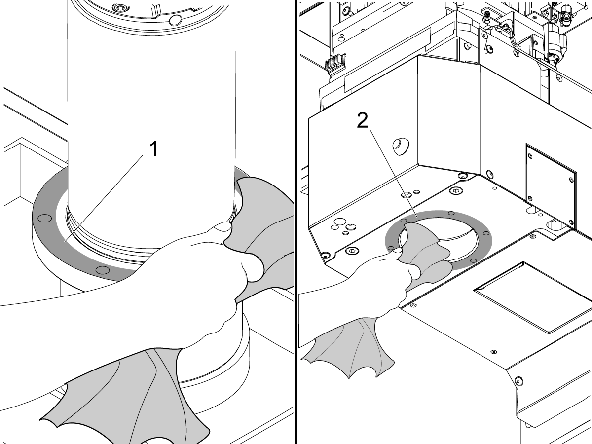
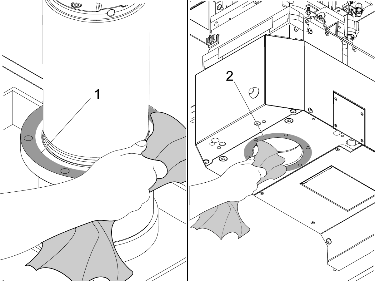
Clean and stone the spindle flange [1] and the spindle head surface [2] where the spindle flange will touch.

2

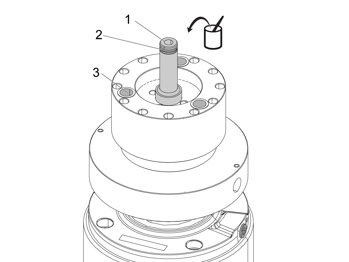
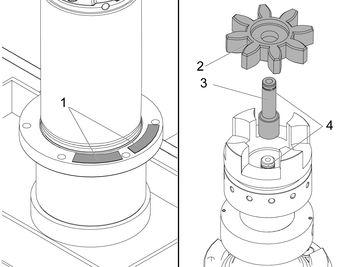
Replace the transfer tube [1] if it is worn or damaged.

Apply a thin layer of lithium grease to these parts:

  • transfer tube [1]
  • transfer tube o-rings [2]
  • pin-coupler bushings [3]

Push the transfer tube [1] back into the spindle pin drive coupling.

Place the shims in the same location as the previous spindle.

Visually check that three bushings [3] are inside the spindle coupler. Make sure they are the same lengths and aren't damaged. 

Spindle Installation

Spindle and Motor Coupling Precautions

Updated

 Caution: Bearing damage will occur if ANY load is placed on the motor shaft or couplings are not aligned during installation.

1

Caution: The motor shaft may become misaligned if spindle installation is done incorrectly.

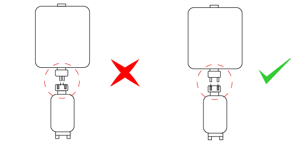
Before installing the spindle loosen the motor mounting bolts at least a half of an inch.

If the pins are misaligned with the coupler, the motor will visibly lift instead of transmitting all of the axis thrust force into the motor shaft and creates damage on the bearings.

2

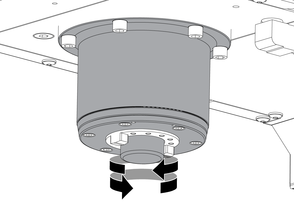
Turn the spindle until the oil fitting port [1] points to the front right of the machine.

Slowly jog the Z Axis in the negative (-) direction over the spindle.

While you jog the Z Axis, use your hand to turn the spindle. If you feel a change in tension, stop immediately. Align the coupler pins to the bushings as closely as possible again.

 Caution: Incorrectly aligned couplers can cause damage to the bearings.

Slowly jog the Z axis in the negative (-) direction.

Make sure the couplers engage smoothly.

Make sure the spindle is centered in the spindle bore. Install (6) spindle screws [1]. Torque the screws. Refer to HAAS FASTENER TORQUE SPECIFICATIONS. 

3

Remove the 1/8" NPT plug [1] from the lubrication port.

Install the 90° spindle lubrication fitting [2].

Install the front air scraper [3].

Connect the spindle lubrication tube.

Perform the VMC - Spindle - Spindle Sweep procedure.

 NOTE: Do not add oil to the spindle casting, even if it had oil before.

4

To align motor to spindle:

Run spindle at 1000 RPM clockwise/forward for 30 seconds.

Run spindle at 1000 RPM counterclockwise/reverse for 30 seconds.

Run spindle at 1000 RPM clockwise/forward for 1 minute.

Snug mounting screws while motor is running.

Note: When motors stops it will jolt to the side and misalign if not snugged down.

Note: The Octavis Vibration Analyzer can be used when aligning motor to find where vibration displacement spike is the smallest.

Torque screws per Haas Torque Specifications.

Run the mill spindle vibration test per Mill - Spindle Vibration - Tolerances.

5

  • Adjust the Tool Release Piston: Refer to VMC - 20/30/40-Taper- TRP - Proximity Sensor - Adjustment.
  • Set Z-Axis Tool Change Offset:
    • Refer to VMC - Side-Mount Tool Changer - Set Parameter 64 - Z-Axis Tool Change Offset. 
    • Refer to Side-Mount Tool Changer - Z-Axis Tool Change Offset - NGC.
  • Set Spindle Orientation Offset:
    • Refer to Side-Mount Tool Changer - Spindle Orientation Offset - Parameter 257.
    • Refer to Side-Mount Tool Changer - Spindle Orientation Offset - NGC.
  • Run the spindle break-in program: Spindle - Break-in Programs - Lathe and Mill.

Re-install the sheet metal assembly.

Testing

1

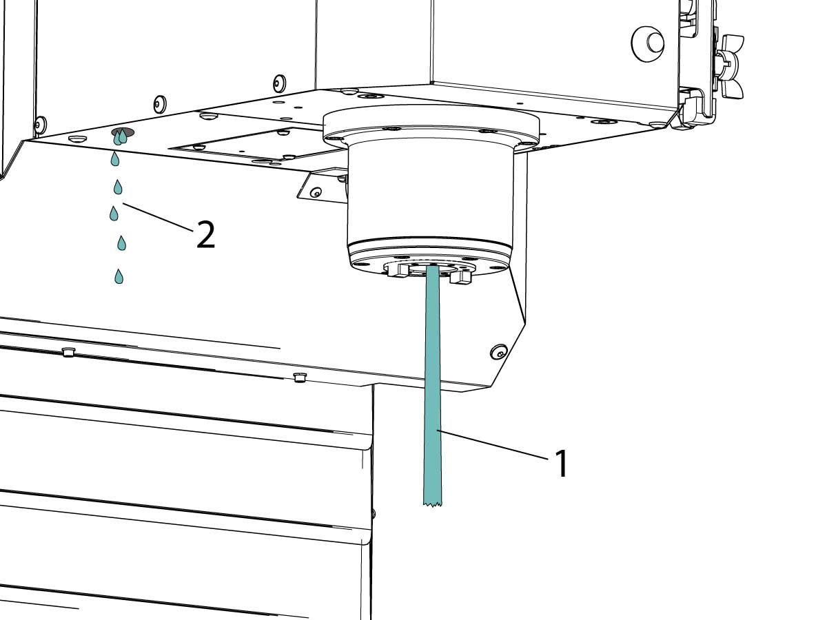
 Push [COOLANT] to start the TSC.

Correct operation is as follows:

  1. Coolant flows correctly from the TSC tool holder [1].
  2. A few drops flow from the vacuum-generator hose [2].

Push [RESET].

Make sure there are no leaks in the air hoses and coolant hoses.

2

For machines with Accessory Tooling Block (ATB) option:

Install the Accessory Tooling Block (ATB) and verify the tool changer arm clears the block during a tool change. 

Note: The image shown is for illustrative purposes only.The ATB position may vary by machine but must not obstruct the tool changer arm during operation.

9.2 40T - Inline Spider Coupling Spindle - Replacement

Recently Updated

VMC - 40-Taper - Inline - Spider Coupling Drive Spindle - Replacement


AD0061

Applies to machines built from: January, 1989

Introduction

The following service video shows how to replace a 40T Inline Spindle.

  NOTE:  This  service video is for reference only and does not replace the written procedure. 

This procedure tells you how to replace a VMC - 40-Taper Inline Spider-Drive Spindle. For a DT/DM machine, refer to the DT/DM - Spider Coupling Drive - Spindle – Replacement -AD0651 procedure.

This Document Applies to the Following Service Kits:

  • 93-30-12005B SPINDLE 40T INLINE 12/15K VMC W/DB
  • 93-30-12005C SPINDLE 40T INLINE 12/15K VMC W/DB
  • 93-30-12008B SPINDLE 40T INLINE 8/10K VMC W/DB
  • 93-30-4018E SPINDLE 40T INLINE 12K 2ND GEN VMC

 Note: If you install the same spindle that you remove or a new spindle, record the location of the spindle shims. Install the spindle shims in the same location and then do the VMC - Spindle - Spindle Sweep procedure.

 Note: If the machine was made between 10/2013 and 2/2016 you must replace the transfer tube.

Spindle Removal

1

Remove the spindle head cover panels. 

2

Remove the front motor shroud panel.

3

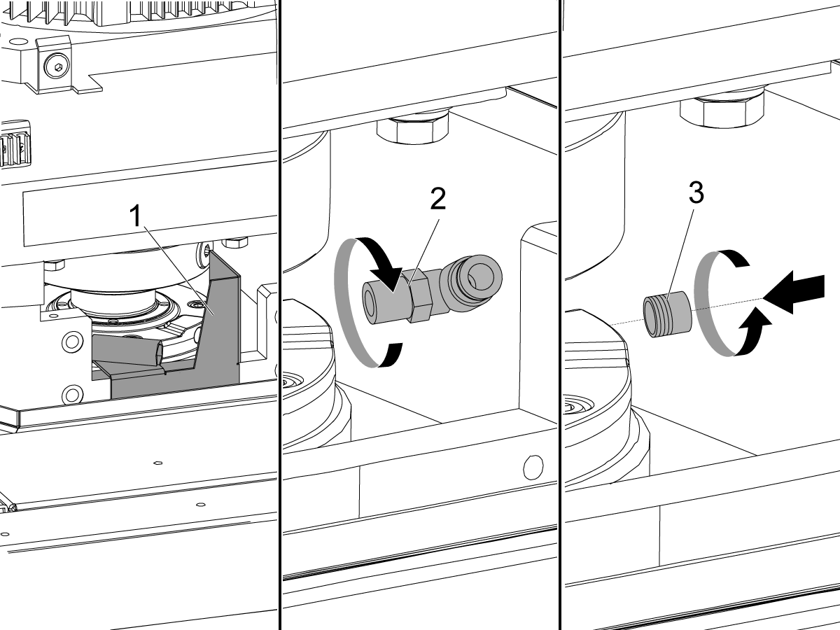
Remove the front air scraper [1].

Disconnect the spindle lubrication tube.

Remove the 90° spindle lubrication fitting [2].

Install a 1/8" NPT plug [3] into the oil fitting port on the spindle. Install the plug [3] flush or below flush with the surface of the spindle.

Loosen the (4) bolts that attach the motor to the mounting plate. Do not remove the bolts.

4

Put an oil pan [3] on the table to catch all oil leaks.

Loosen the (6) spindle screws [1] approximately (2) turns.

Install the protective cap [2] over the spindle nose.

 Caution: The protective cap is necessary. It prevents damage to the spindle when it touches the table in the next step.

Jog the Z Axis in the negative (-) direction until the spindle touches the table. If the spindle does not touch the table, put a wooden or aluminum block under the spindle.

Remove the (6) spindle screws.

Jog the Z Axis in the positive (+) direction until the spindle is fully out of the spindle head and it can be removed. 

5

Remove the shims [1].

Remove these parts:

  • the spider coupling [2]
  • the transfer tube [3]
  • the o-rings [4]

Spindle Installation Preparation

1

Jog the Z Axis in the positive (+) direction to the top of travel.

Clean and stone the spindle flange [1] and the spindle head surface [2] where the spindle flange will touch.

2

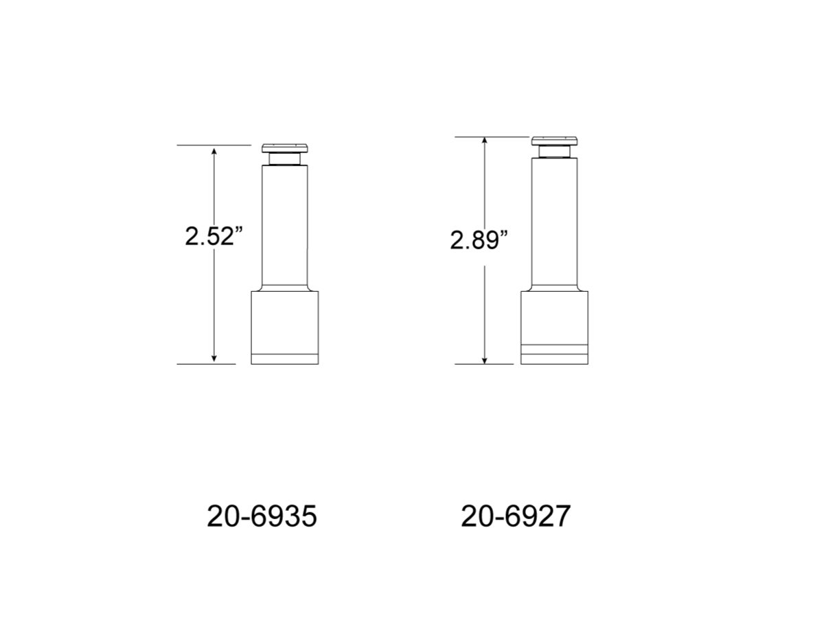
Use the correct transfer tube for your machine.

  • 40-Taper; 8K/10K/12K RPM; inline spindle; use 20-6935: SPINDLE TRANSFER TUBE INLINE 12K
  • 40-Taper; 15K RPM; inline spindle: use 20-6927: SPINDLE TRANSFER TUBE INLINE 15K RPM

3

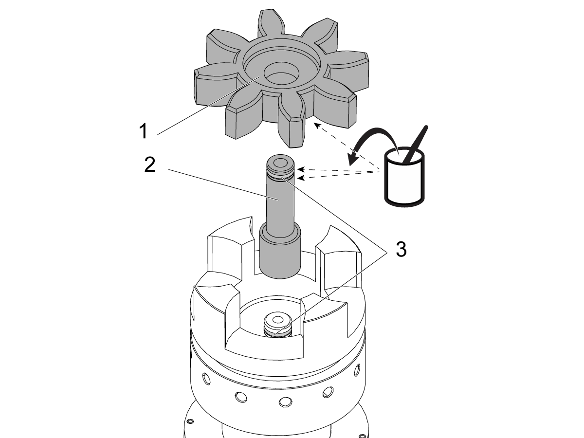
Apply a thin layer of lithium grease to these parts:

  • spider coupling [1]
  • transfer tube [2]
  • o-rings [3]

Install the transfer tube into the spindle.

Install the spider coupling.

Place the shims in the same location as the previous spindle.

Spindle Installation

Spindle and Motor Coupling Precautions

Updated

 Caution: Bearing damage will occur if ANY load is placed on the motor shaft or couplings are not aligned during installation.

1

Caution: The motor shaft may become misaligned if spindle installation is done incorrectly.

Before installing the spindle loosen the motor mounting bolts at least a half of an inch.

If the pins are misaligned with the coupler, the motor will visibly lift instead of transmitting all of the axis thrust force into the motor shaft and creates damage on the bearings.

2

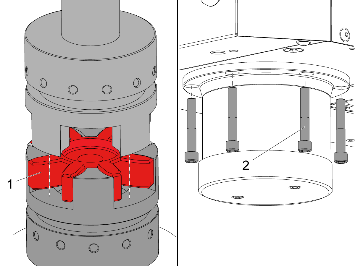
Slowly jog the Z Axis in the negative (-) direction over the spindle.

Make sure the spindle coupler and the motor coupler align with the spider coupler [1].

Caution: Incorrectly aligned couplers can cause damage to the bearings.

Slowly jog the Z axis in the negative (-) direction.

Make sure the couplers engage smoothly.

Make sure the spindle is centered in the spindle bore. Install (6) spindle screws [2]. Torque the screws. Refer to HAAS FASTENER TORQUE SPECIFICATIONS. 

3

Remove the 1/8" NPT plug [1] from the oil fitting port on the spindle.

Install the 90° spindle lubrication fitting [2].

Install the front air scraper [3].

Connect the spindle lubrication tube.

Do the VMC - Spindle - Spindle Sweep procedure.

 Note: Do not add oil to the spindle casting, even if it had oil before.

4

To align motor to spindle:

Run spindle at 1000 RPM clockwise/forward for 30 seconds.

Run spindle at 1000 RPM counterclockwise/reverse for 30 seconds.

Run spindle at 1000 RPM clockwise/forward for 1 minute.

Snug mounting screws while motor is running.

Note: When motors stops it will jolt to the side and misalign if not snugged down.

Note: The Octavis Vibration Analyzer can be used when aligning motor to find where vibration displacement spike is the smallest.

Torque screws per Haas Torque Specifications.

Run the mill spindle vibration test per Mill - Spindle Vibration - Tolerances.

5

  • Adjust the Tool Release Piston: Refer to VMC - 20/30/40-Taper- TRP - Proximity Sensor - Adjustment.
  • Set Parameter 64 (CHC): Refer to VMC - Side-Mount Tool Changer - Set Parameter 64 - Z-Axis Tool Change Offset.
  • Set Parameter 64 (NGC): Refer to VMC - Side-Mount Tool Changer - Set Parameter 64 - Z-Axis Tool Change Offset.
  • Set Parameter 257 (CHC): Refer to Side-Mount Tool Changer - Spindle Orientation Offset - Parameter 257.
  • Set Parameter 257 (NGC): Refer to Side-Mount Tool Changer - Spindle Orientation Offset - Parameter 257.
  • Balance the spindle: Refer to Spindle - Balance Instructions.
  • Run the spindle break-in program: Spindle - Break-in Programs - Lathe and Mill

Re-install the sheet metal assembly.

Testing

1

 Push [COOLANT] to start the TSC.

Correct operation is as follows:

  1. Coolant flows correctly from the TSC tool holder [1].
  2. A few drops flow from the vacuum-generator hose [2].

Push [RESET].

Make sure there are no leaks in the air hoses and coolant hoses.

9.3 40T - Spindle - Troubleshooting

Recently Updated

Mill Spindle - Troubleshooting Guide


TG0101

Revision B - 11/2025

Introduction

Download and fill out the Spindle Inspection Report Checklist below before replacing any parts.

Spindle Inspection Report Checklist

Symptom Table

Symptom Possible Cause Corrective Action
Spindle not turning and at Power On:  A Warning appears " The spindle may be rotating freely without power... " The software version is outdated. Check the software version to be 100.20.000.1200 or higher. Contact your Haas Factory Outlet to have the software updated.
Noise during rigid tapping. A NGC software error in version 100.17.000.xxx that caused a noticeable growling noise during rigid tapping, particularly with coarse pitch threads. Update software to the latest version.
Problems with the spindle encoder. Look for runout, loose mounting screws or shaft clamps, and any other obvious problems. Spindle Non-Contact Encoder (NCE) - Troubleshooting Guide - NGC
The Spindle is seized or it won't turn. The spindle has been crashed and now damage. Review alarm history for indications of a crash, check for visual damage to the spindle
There is heavy side loads causing the cap to gall the shaft. Check for clearance all the way around with a piece of 0.001” shimstock; loosen the cap, re-center and tighten.
The spindle lubrication system is not functioning correctly. Inspect the spindle lubrication system.
Spindle installed incorrectly Check Motor coupler for damage or indentations at the pin interfaces. Contact local HFO about issue including relevant pictures of the spindle to motor coupler.
The spindle  temperature exceed 140° F (60° C) The spindle lubrication system does not function correctly. Check for a clog in the spindle lube pump and verify the type of oil.
The spindle makes an unusual noise. The spindle drive belt is worn or damaged. Check the spindle drive belt for damaged.
The encoder pulleys or drive belt are worn or damaged. Check the encoder pulleys and belt.
The spindle lubrication system does not function correctly. Check for a clog in the spindle lube pump and verify the type of oil.

The surface finish shows chatter, or the spindle vibrates.

Alarm 966 EXCESSIVE PART/TOOL IMBALANCE.

The Main Processor PCB standoff hardware is loose or the Control Cabinet mounting hardware is loose or causing a bind.   Tighten the Main Processor PCB standoff hardware. Loosen the Control Cabinet mounting hardware, snug the hardware, then torque down the hardware.
The tool or tool holder may be too long for the application. Longer tools are less stable than shorter tools. Always use the shortest tool possible, and remember that a 10% reduction in the length-to-diameter ratio results in a 25% increase in tool stiffness. Unless absolutely necessary, the tool's stick-out from the holder should not be more than 3 times longer than its diameter.
The spindle drive belt is worn or damaged. Check the spindle drive belt.
The encoder pulleys or drive belt are worn or damaged. Check the encoder pulleys and belt.
The toolholder is fretting. Verify the length of the tool with the manufacturer's specifications.
The drawbar force is incorrect. Make sure the drawbar clamp force is correct. Refer to: VMC - Spindle - Drawbar - Force Measurement
The fixture does not support the part. Adjust the cutting load or program.
The tool is unbalanced. Balance the tool holder with the cutting tool in it. If you cannot balance the tool assembly, replace it with one that you can balance.
Excessive Endmill Runout - Mill. Tool runout should not exceed 0.0003" (0.076 mm). To check the tool runout, place a dial indicator on the tool, and then rotate the spindle by hand.
The spindle bearings are damaged. Perform a vibration analyzer.
The spindle is not balanced. Contact your HFO to balance the spindle.
Tools stick or do not come out of the spindle easily. The tool stayed in the spindle for hours while the machine was not in operation. Make sure a tool is not in the spindle when the machine is not in operation.
The volume of air supplied to the machine is not sufficient. Refer to: New Machine / Pre-Installation information for the correct air requirements.
The drawbar force is incorrect. Make sure the drawbar clamp force is correct.
The toolholder is fretting. Damage tool shank or spindle taper. Verify the length of the tool with the manufacturer's specifications. Maintain and inspect tool holders, and spindle taper.
There is no grease on the pull stud. Lubricate the pull stud.
(Through-spindle coolant only) Some coolants cause tools to stick. Coolants containing paraffin waxes can causing sticking tools when using high pressure Through Spindle Coolant with small orifice tooling. Test with a different type of coolant.
The spindle is getting too hot. Test the spindle lubrication system. Lack of, or excessive oil will create heat in the spindle.
Long gage length tooling. Stub up the tools to the extent possible. Reduce depth of cut. Use dynamic tool path and constant cutter engagement.
While running there is bearing Noise: squealing, screeching or skating. Noise from imbalance and vibration Make sure the tools are balanced.
Squealing noises from the TSC union. Check the TSC union.
Rubbing noises; Heat at the front cap. Spindle cartridge has been bumped there is a chance the front cap has been pushed to one side and is rubbing on the nose of the spindle shaft. Check for clearance all the way around with a piece of 0.001” shimstock; loosen the cap, re-center and tighten.
Noises during tool change. Some models have had the precharge circuit eliminated. This is a reliability improvement but a noise can be heard when the TRP contacts the drawbar or the release ring. This is normal.
The spindle oscillates during spindle orientation. The Wye contactor (if equipped) coil is not receiving power. Make sure the Wye/Delta contactors are operating correctly. Refer to: Wye-Delta Contactor - Troubleshooting Guide.
The spindle motor wiring is incorrect. The spindle motor wiring is incorrect. Refer to: Spindle Motor - Wiring Configurations.
The vector drive is defective. The vector drive is defective. Refer to: Vector Drive - Troubleshooting Guide.
Alarm 174 Tool Load Exceeded Tool Load limit incorrect View the Advanced Tool Managment (ATM) tab to adjust user defined tool load limit
Aggressive feedrates Adjust your program for a more conservative feedrate
Machine is experiencing surface finish issues Preload set to the bearings may be incorrect

Perform the Spindle Deflection Test - Mill procedure for preload verification

NOTE: Only perform this procedure AFTER all other troubleshooting steps outlined in the Mill Spindle Inspection Report, linked at the top of this page, have been performed. 

Lube line slips out of fitting easily.  Plastic fitting has failed. Replace fittings with updated steel version. Order PN 58-2196. 

Lubrication

Corrective Action:

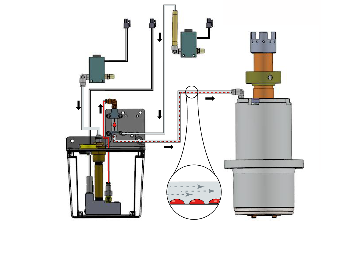
Insufficient or excessive oil supply to the spindle bearings can cause the spindle to overheat. Using the incorrect spindle lubrication oil on the spindle bearings can cause the spindle to overheat. Make sure you use the correct spindle lubrication (SHC 625) and the air pressure to the spindle is correct.

Inspect all tubing, hoses and fittings in the lubrication system for leaks. Check for puddles of oil to help locate leaks.

Go to Haas Spindle minimum lubrication troubleshooting for additional troubleshooting information

Go to Mechanical Bijur Lube Pump - Troubleshooting Guide for additional troubleshooting information.

Drive Belt

Corrective Action:

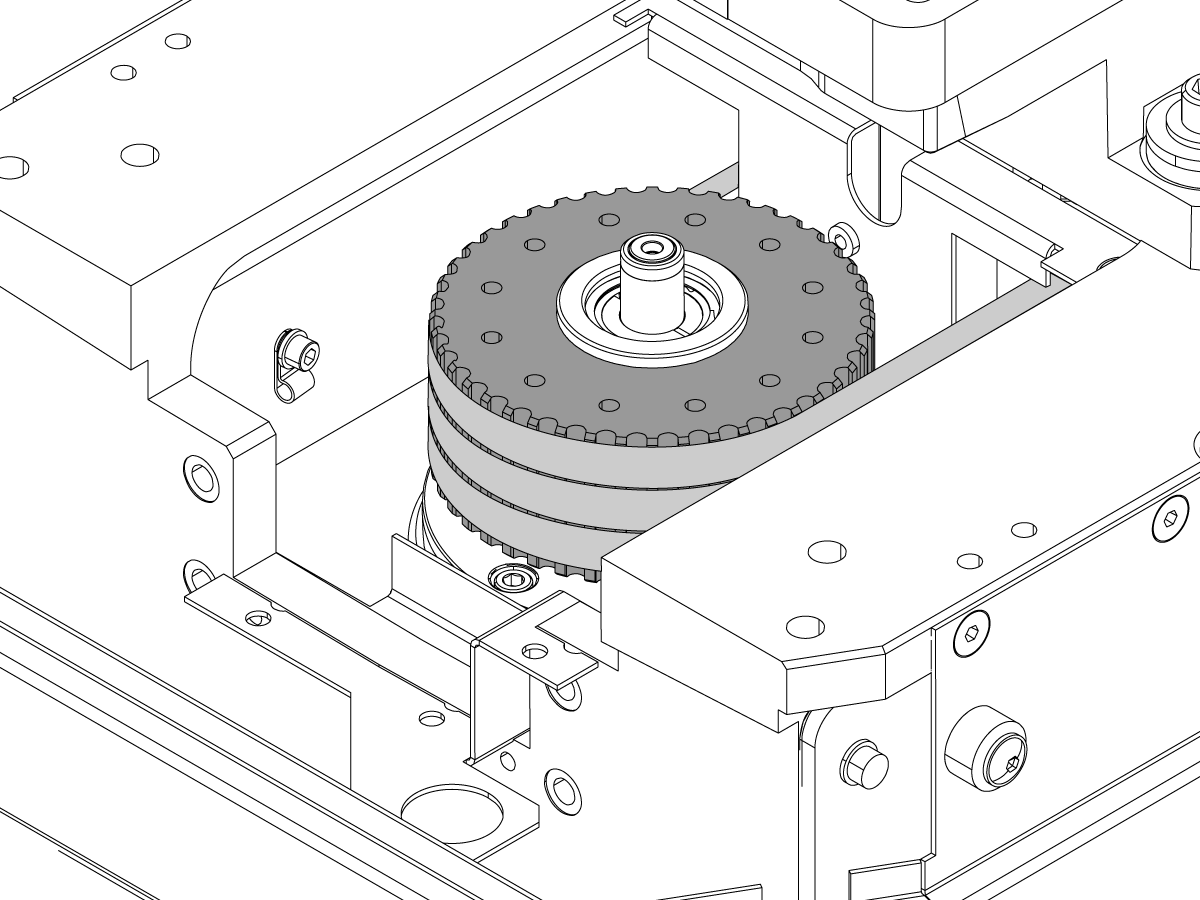
Power off, lock and tag out machine. Remove the spindle head covers. Disconnect the air supply to the machine. Remove the four 3/8-16 SHCS on the TRP. Remove the TRP and set it aside.

Inspect the spindle drive belts and pulleys for damage: Look for frayed, stretched or broken belts, and damaged or stripped cogs on the inside surface of the belt. Refer to the Drive Belt - Troubleshooting Guide.

Encoder Pulley/Belt

Corrective Action:

Make sure the encoder belt is adjusted correctly and is not damaged. Replace a damaged or worn belt.

Make sure the encoder pulley is not worn. Make sure the set screw is tight.

Reference Spindle Non-Contact Encoder (NCE) - Troubleshooting Guide - NGC for more information about the encoder assembly.

Drawbar Force

Corrective Action:

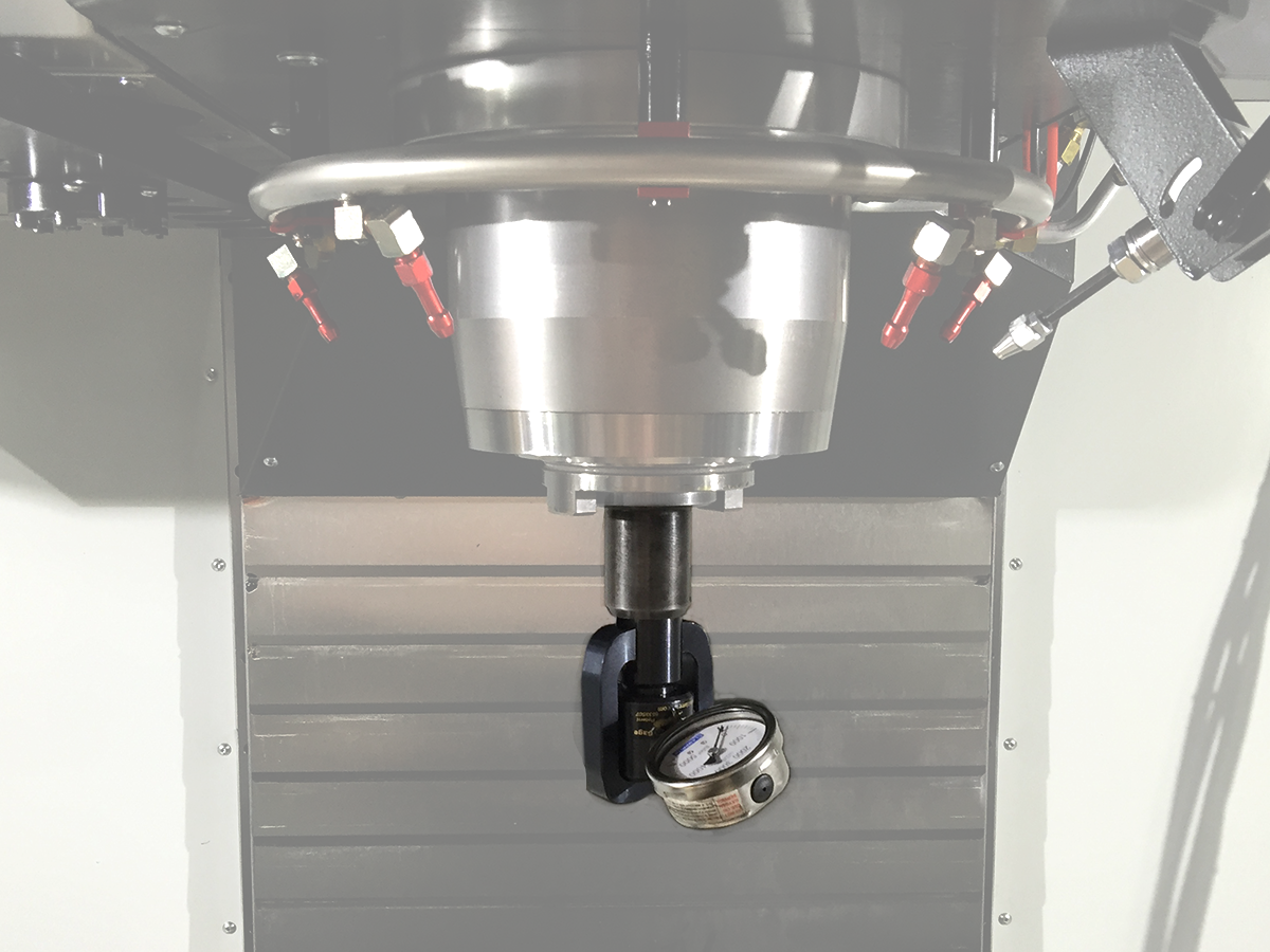
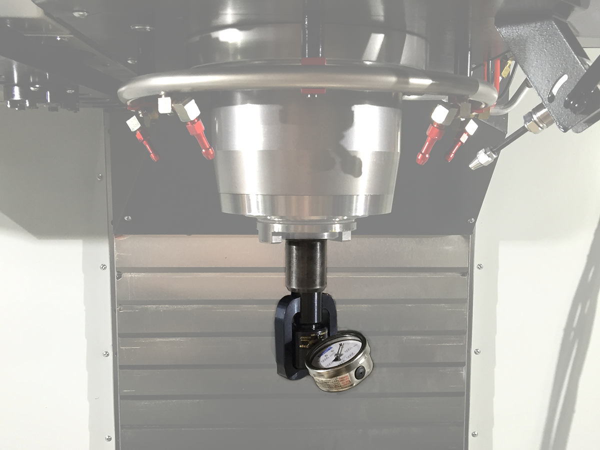
Use a drawbar force gauge in the spindle to measure the clamp force. Refer to Spindle - Drawbar Force Reference Table.

If the drawbar force is incorrect, go to Spindle - Drawbar - Troubleshooting Guide.

Coolant

Corrective Action:

If the machine has through-spindle coolant (TSC), different types of coolant can cause the toolholder to stick in the spindle. Consider a different type of coolant if the symptom persists.

Workholding

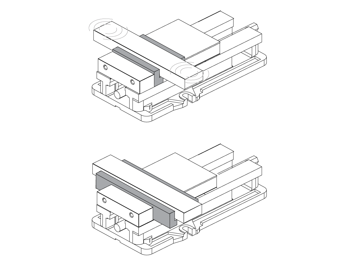
If the workholding does not adequately support the part, it can cause chatter.

Corrective Action:

Stiffen the workholding if possible.

Lower the cutting load with adjustments to the tool selection, or the program.

Balance

Corrective Action:

Make sure the spindle is balanced. Your local HFO can balance these spindles:

  • All belt-driven spindles
  • Inline spindles made after August, 2016

All tooling that runs over 10K RPM must be balanced. Do not exceed the manufacturer recommendations for special tooling.

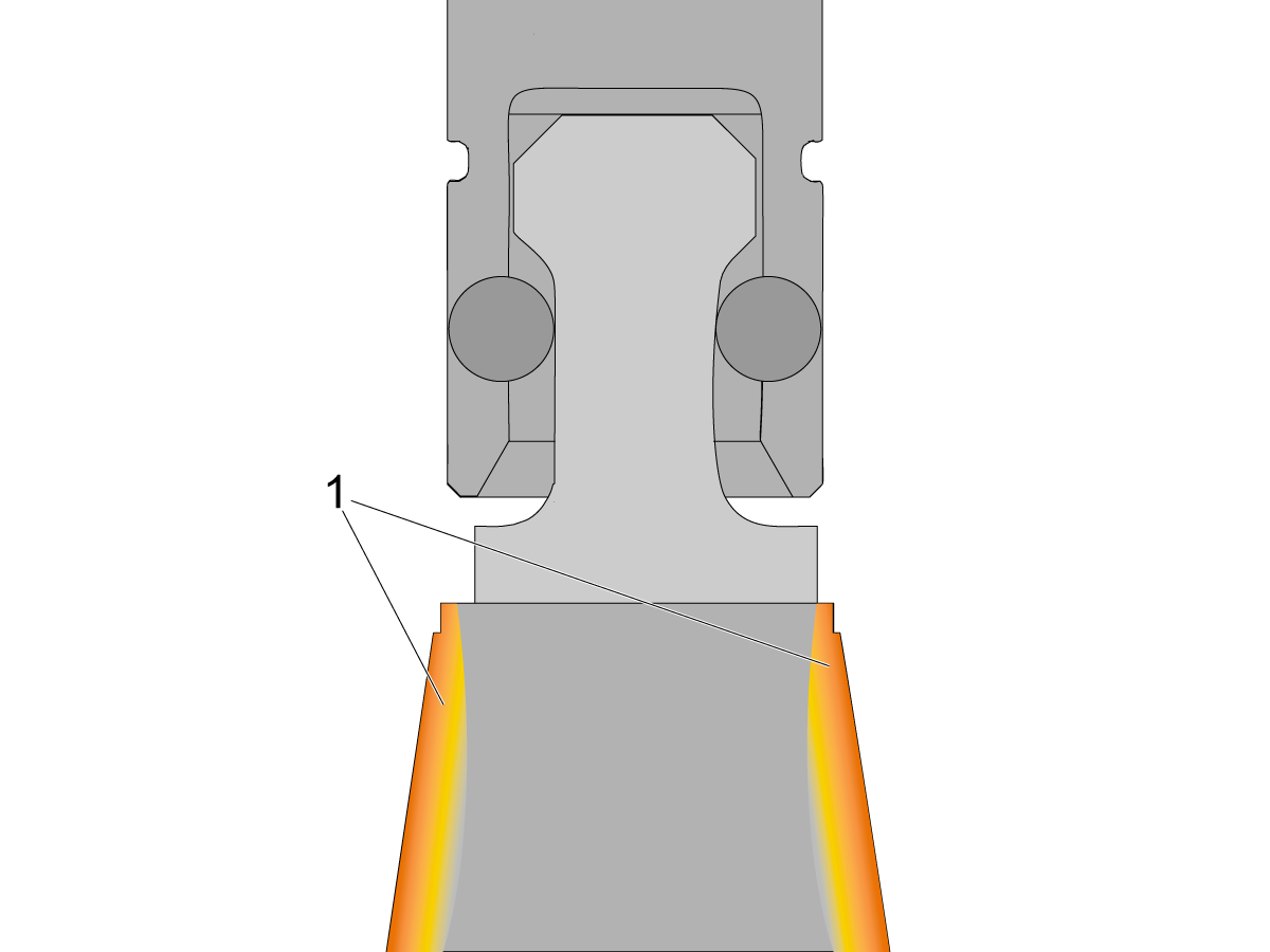
Toolholder Is Sticking

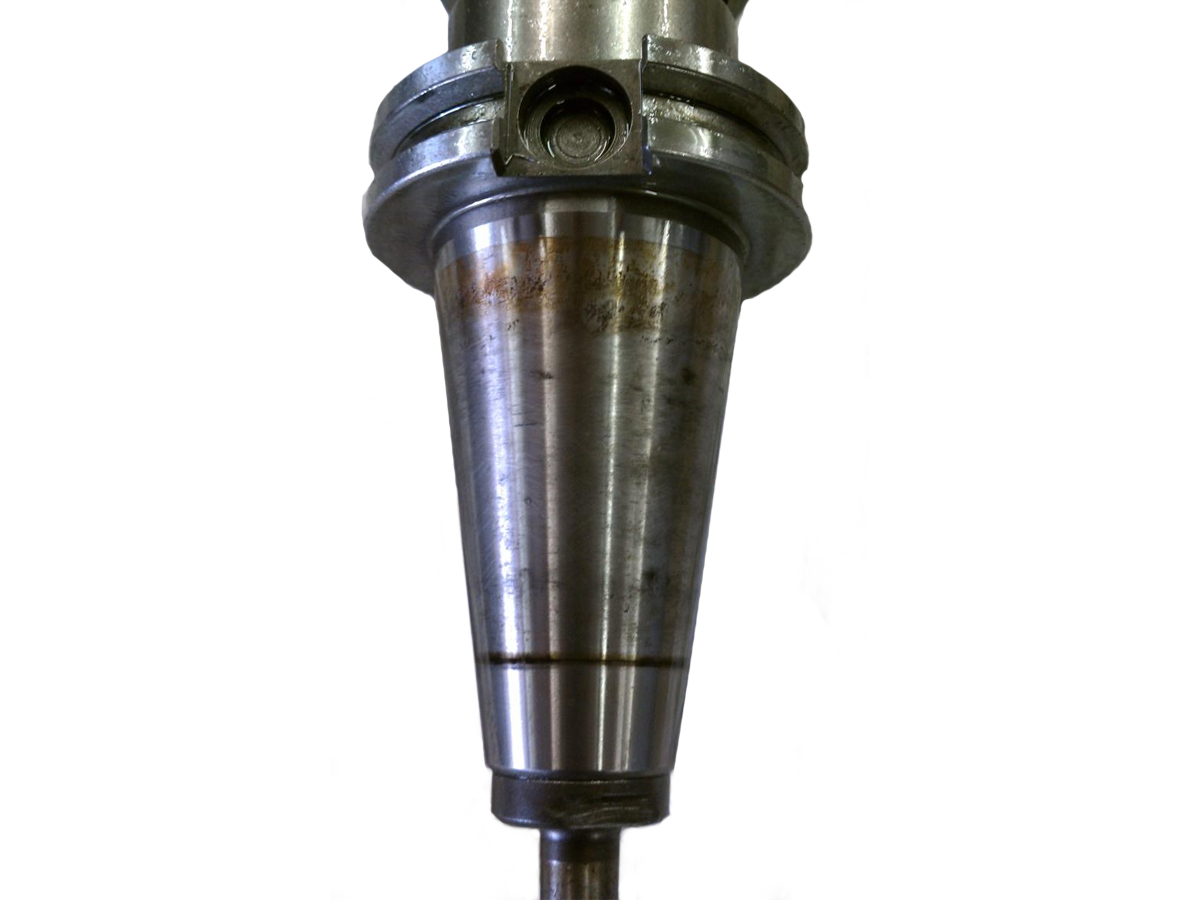
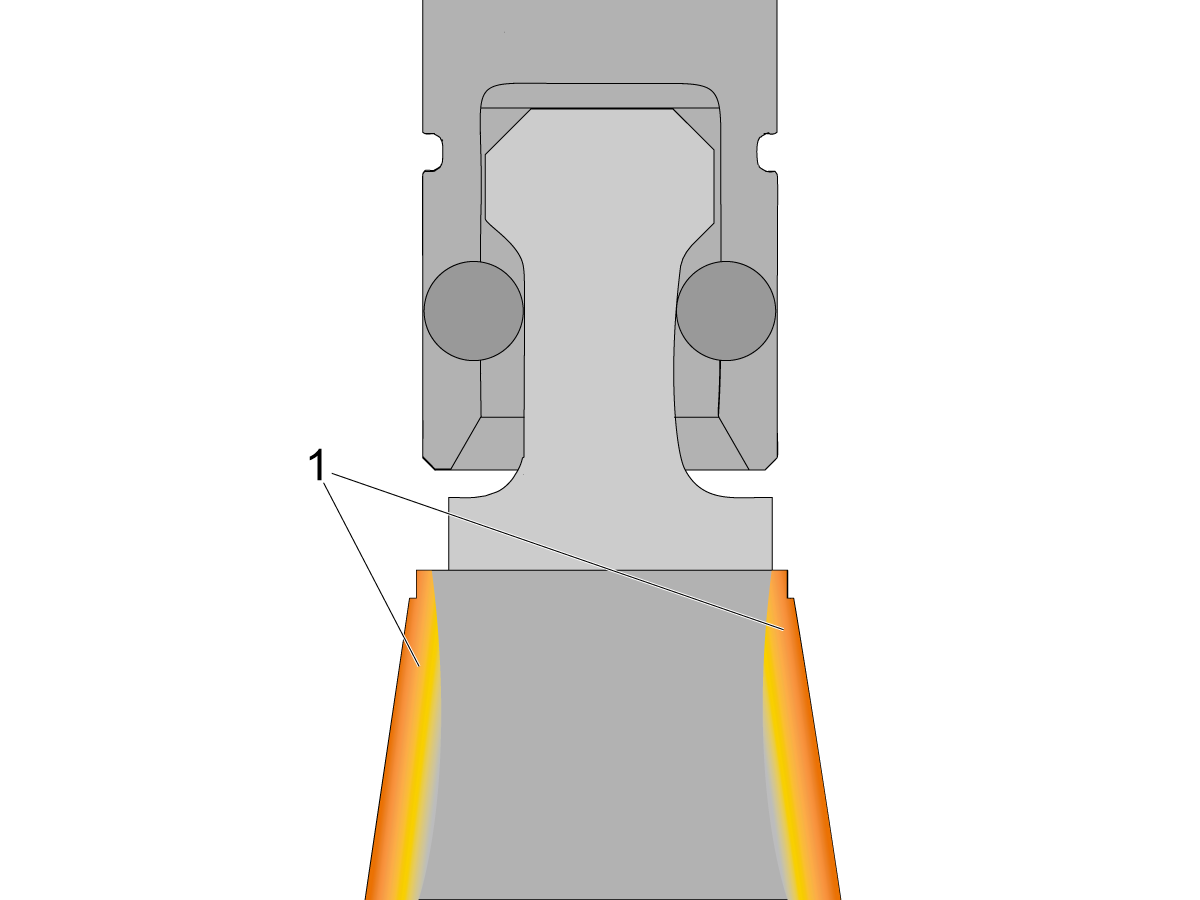
This effect can occur while the machine is in operation if a cold toolholder is placed into a warm spindle taper. This creates thermal expansion [1] on the sides of the toolholder and makes it stick in the spindle taper before it is released.

A common example is if you change from a hot cutter to the cool spindle probe to check your part at the end of a cycle. If the cool probe is left in the hot spindle overnight, it will make a "popping" noise when it is released.

Corrective Action:

Clean the toolholders and spindle taper. Check for damaged toolholders before you put them back in the machine. A damaged toolholder can cause damage to the spindle taper and create tool runout or problems with finish.

Make sure the pull stud is lubricated. Refer to the Mill - Tooling - Maintenance procedure.

Toolholder Is Fretting

Corrective Action:

Look for fretting on the toolholders. Long tools can cause fretting on toolholders if you use them aggressively. If there is fretting on the toolholder, or if the symptom persists, go to Spindle - Drawbar - Troubleshooting Guide.

Bearings

Corrective Action:

Damaged bearings in the spindle can cause finish issues on the part. Contact your local HFO for a vibration analysis to see if the bearings are damaged.

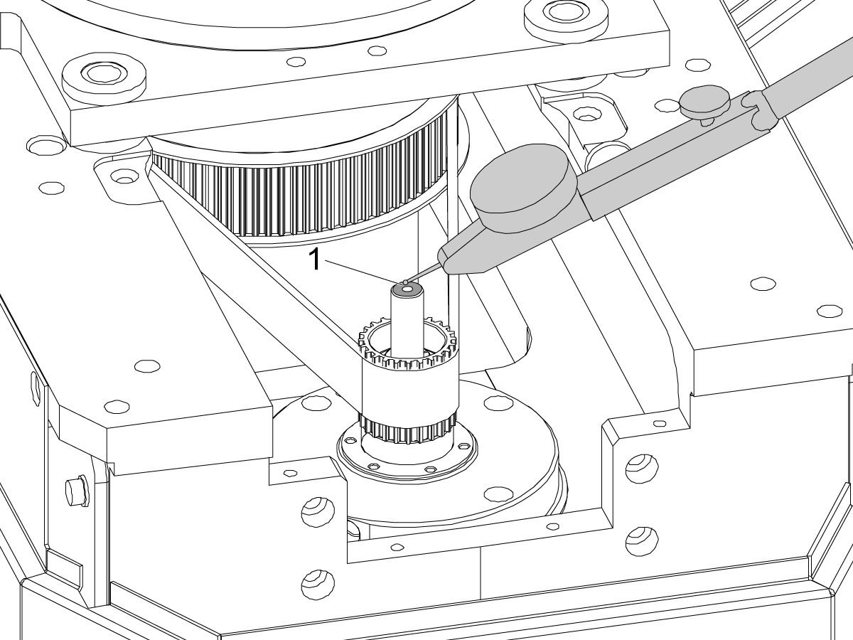
Axial Check

For belted spindles, place the indicator on the top face of the drawbar to check the axial runout.

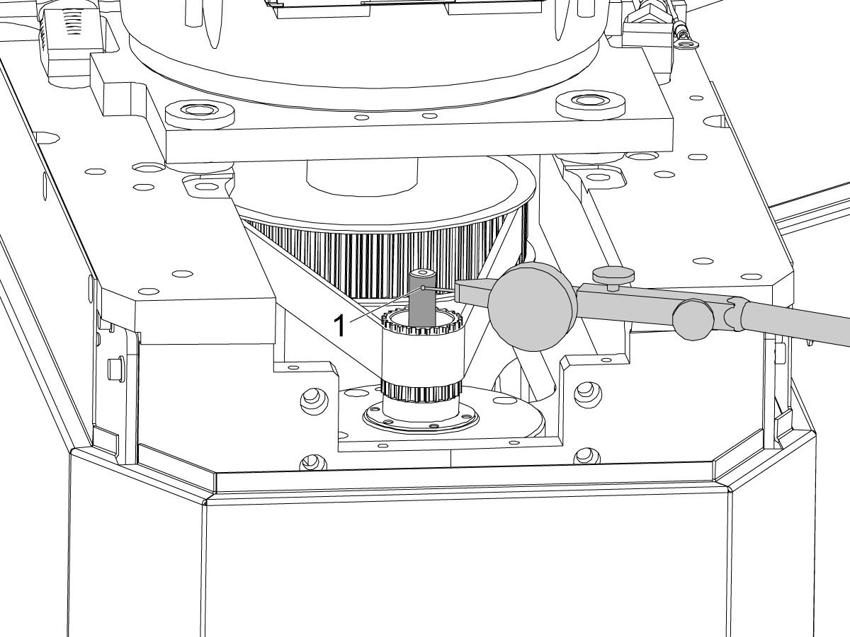
Radial Check

For belted spindles, place the indicator on the shaft of the drawbar to check the radial runout.

Spindle Temperature Check

1

 Note: DO NOT operate the spindle without a dummy tool in the taper [1].  Running the spindle without a tool will damage the bearings.

 Note: Perform a spindle lubrication test and run spindle warm-up program before proceeding.

Place a piece of masking tape [2] on the front side of the spindle. Draw a black dot [3] in the center of the tape. Take the thermal readings from this location.

2

Download the program listed below onto a USB.

Spindle Temp Test:

O12345

Install the USB with the downloaded program into the USB port on the side of the pendant.

Load and run program O12345.

3

After the program is done running (40 minute run time), use a temperature gun [1] to measure the spindle temperature.

Verify the spindle temperture does not exceed 140° F (60° C). 

9.4 40T - Spindle Drawbar - Troubleshooting

Recently Updated

Spindle - Drawbar - Troubleshooting Guide


TG0132

Revision A - 12/2025

Introduction

  1. Drawbar
  2. Toolholder
  3. Retention balls
  4. Pull stud
  5. Belleville springs

Symptom Table

Symptom Possible Cause Corrective Action
The toolholder frets in the taper. The tool pulls out of the taper. Check for damaged Belleville spring washers.
The part has a poor finish. The tool length is too long. Refer to the tool manufacturer's specifications.
The toolholder drops before the tool changer can grab it. The clamp force on the toolholder is too low, or the TRP pre-charge is not set correctly. Check the clamp force and pre-charge air pressure.
(TSC Only) Excessive coolant comes out of the coolant tube behind the spindle. The carbide insert on the drawbar is damaged. Check the carbide insert in the drawbar and TRP for damage.  Note: If the machine has a pre-charge system check that the pre-charge air pressure is set correctly.  Refer to the tool release piston pre-charge adjustment procedure: VMC - 30/40-Taper - Tool Release Piston - Pre-charge - Adjustment
The drawbar does not release the toolholder smoothly. The pull stud angle is pitted or damaged. Check the pull stud for damage.
The TRP sensor(s) are not aligned. Align the tool release piston sensor(s).
The air pressure or volume to the TRP is too low. Check the air pressure and volume.
The drawbar retaining balls are dry. Apply RED-i grease to the retaining balls.
Toolholder makes a "popping" noise when it is released. The toolholder and spindle taper are dirty. Clean the taper.

40T and 50T Belted Spindles

Pull studs will not enter into spindle taper, carbide tips on drawbar and TRP are damaged prematurely,

And possibly one of the following alarms:

Alarm 130 Tool Unclamped
Alarm 134 Tool Unclamp Fault
Alarm 9970 Unexpected Tool Release

There is a small delay from the I/O PCB that causes the pre-charge solenoid not to turn OFF. Order service kits 93-3451 & 93-3452 and follow the Low Load Solenoid Valve Kit - Installation procedure.
Service replacement drawbar will not fit into spindle shaft.  Replacement drawbar needs to be straightened before installation.  Roll replacement drawbar along a high-precision granite table to identify bends or waves in drawbar spring. Mark high spots. Clamp drawbar firmly and use a mallet to tap spring back into place. Take care not to damage drawbar. If drawbar cannot be straightened with this method, contact the service department for a replacement. 

Toolholder Is Fretting

Corrective Action:

Verify that the tool length, axis feed, and spindle RPM are correct according to the tooling manufacturer's recommendations.

Drawbar Force

Corrective Action:

Check the clamp force with a clamp force measuring tool and refer to the Drawbar Force Reference Table. If the pull force is low, the drawbar is faulty.

Belleville Springs

Corrective Action:

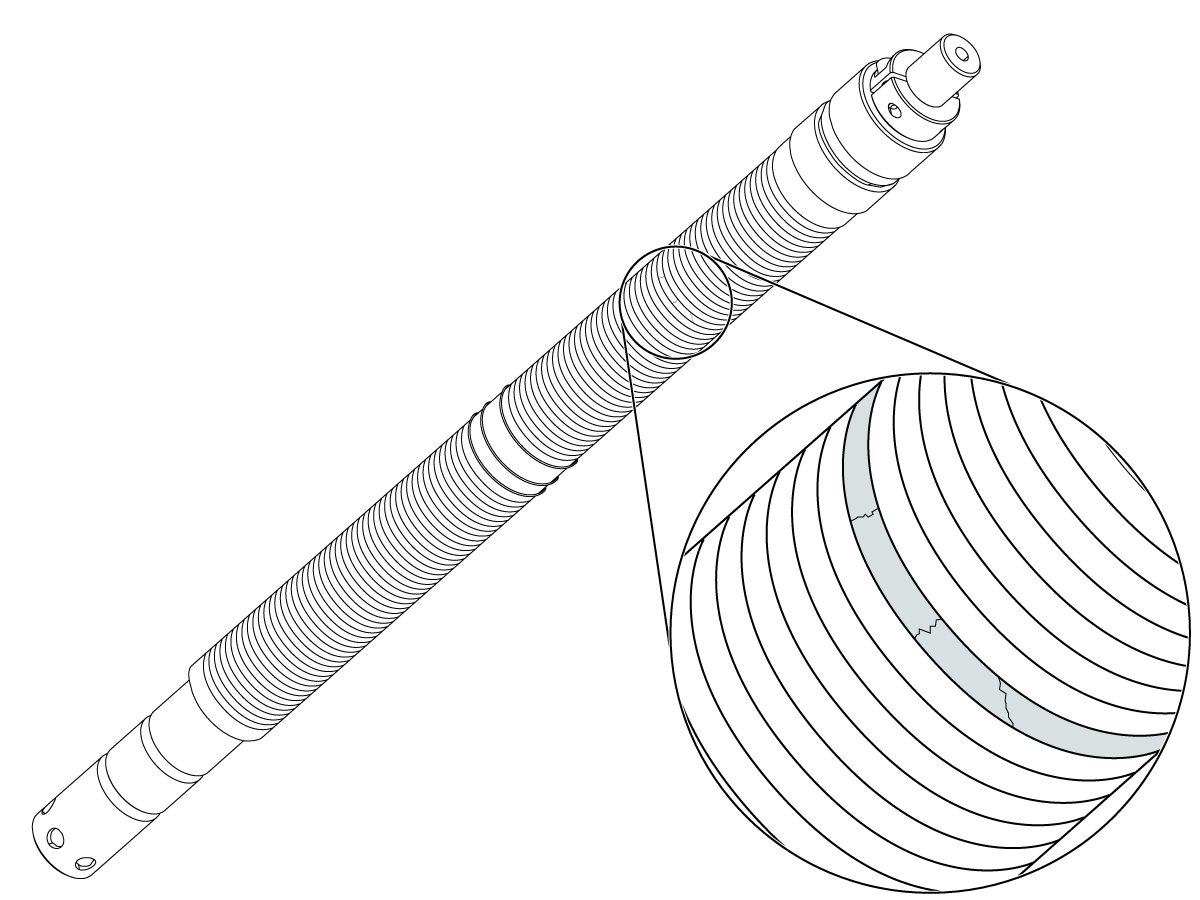
If the Belleville springs on your drawbar are damaged, you must replace the drawbar. The drawbar in inline spindles cannot be removed. If the drawbar in an inline spindle is damaged, you must replace the entire spindle assembly.

Check for tools getting stuck in the spindle,  inspect the pull studs and spindle taper for damage.

Pull Studs

Corrective Action:

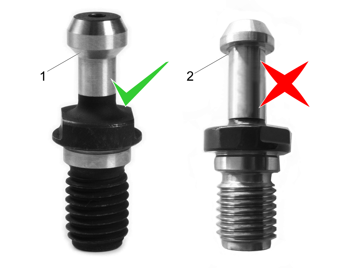
Remove the toolholder from the spindle. Check for damage to the pull stud. The pull stud must have a 45° angle [1].

Ball marks on the edge of the pull stud indicate that the drawbar does not open completely.

Refer to the TRP clamp/unclamp sensor adjustment procedure.

TRP Sensor(s)

Corrective Action:

Refer to the TRP clamp/unclamp sensor adjustment procedure.

Air Pressure

Corrective Action:

Verify that the air pressure to the TRP solenoid [1] is 90-psi (6.21 bar).

If the volume is correct, there should be only a 10-psi (0.69 bar) air pressure drop during a tool change. Use an inline air gauge to measure the change in air pressure.

Check for kinks or splits in the air hose that goes to the TRP assembly [2].

Make sure the volume of air supplied to the machine is sufficient. Refer to New Machine Setup/Pre-Installation.

Lubrication

Corrective Action:

To grease the retaining balls, put a ball of RED-i grease on top of a pull stud.

Put the toolholder into the spindle. Clamp and unclamp (4) or (5) times to load the grease onto the retaining balls.

Remove the toolholder. Wipe excess grease from the toolholder and spindle taper.

Contamination

Corrective Action:

Clean the toolholders and spindle taper. Check for damaged toolholders before you put them back in the machine. A damaged toolholder can cause damage to the spindle taper and create tool runout or problems with finish.

Recently Viewed Items

You Have No Recently Viewed Items Yet

Feedback
Haas Logo

Haas Delivered Price

This price includes shipping cost, export and import duties, insurance, and any other expenses incurred during shipping to a location in France agreed with you as a buyer. No other mandatory costs can be added to the delivery of a Haas CNC Product.

KEEP UP WITH THE LATEST HAAS TIPS AND TECHNOLOGY...

Sign up now!   

HAAS TOOLING ACCEPTS THE FOLLOWING:

  • Service & Support
  • Owners
  • Request Service
  • Operator Manuals
  • Haas Parts
  • Rotary Repair Request
  • Pre-Install Guides
  • Shopping Tools
  • Build & Price a New Haas
  • Available Inventory
  • The Haas Price List
  • CNCA Financing
  • About Haas
  • Accessibility Statement
  • DNSH Statement
  • Export Compliance
  • Careers
  • Certifications & Safety
  • Contact Us
  • History
  • Terms & Conditions
  • Haas Tooling Terms & Conditions
  • Privacy
  • Warranty
  • Haas Community
  • Haas Certification Program
  • Haas Motorsports
  • Gene Haas Foundation
  • Haas Technical Education Community
  • Events
  • Join the Conversation
  • Facebook
  • X
  • Flickr
  • YouTube
  • LinkedIn
  • Instagram
  • TikTok
© 2026 Haas Automation, Inc – CNC Machine Tools
This site is protected by reCAPTCHA and the Google Privacy Policy and Terms of Service apply.

2800 Sturgis Rd., Oxnard, CA 93030
Toll Free: (888) 817-4446 / Fax: 805-278-8554