-
machines
-
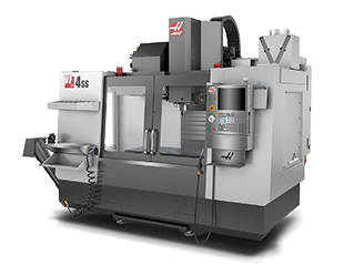 Vertical Mills
Vertical Mills
Vertical Mills -
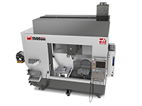 Multi-Axis Solutions
Multi-Axis Solutions
Multi-Axis Solutions -
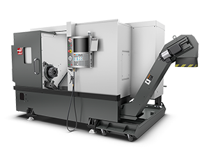 Lathes
Lathes
Lathes -
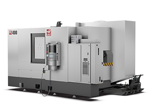 Horizontal Mills
Horizontal Mills
Horizontal Mills -
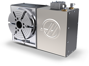 Rotaries & Indexers
Rotaries & Indexers
Rotaries & Indexers -
Special Series
Special Series -
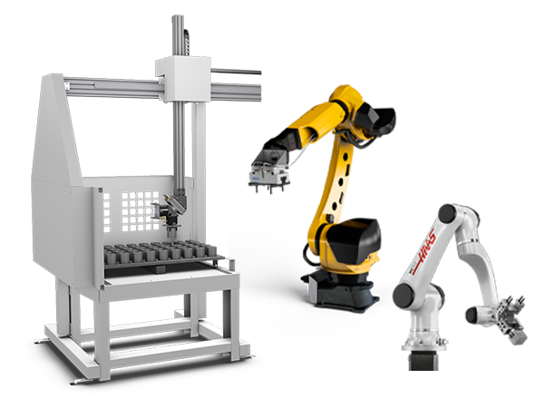 Automation Systems
Automation Systems
Automation Systems -
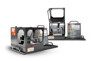 Desktop Machines
Desktop Machines
Desktop Machines -
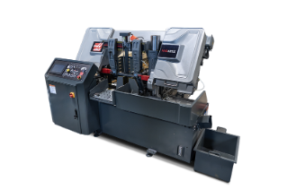 Shop Equipment
Shop Equipment
Shop Equipment
SHOPPING TOOLSWANT TO TALK TO SOMEONE?A Haas Factory Outlet (HFO) can answer your questions, and walk you through your best options.
CONTACT YOUR DISTRIBUTOR > -
-
Options
-
 Spindles
Spindles
Spindles -
 Tool Changers
Tool Changers
Tool Changers -
 4th- | 5th-Axis
4th- | 5th-Axis
4th- | 5th-Axis -
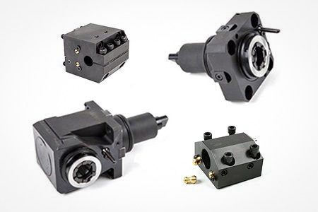
 Turrets & Live Tooling
Turrets & Live Tooling
Turrets & Live Tooling -
 Probing
Probing
Probing -
 Chip & Coolant Management
Chip & Coolant Management
Chip & Coolant Management -
 The Haas Control
The Haas Control
The Haas Control -
 Product Options
Product Options
Product Options -
 Tooling & Fixturing
Tooling & Fixturing
Tooling & Fixturing -
 Workholding
Workholding
Workholding -
 5-Axis Solutions
5-Axis Solutions
5-Axis Solutions
SHOPPING TOOLSWANT TO TALK TO SOMEONE?A Haas Factory Outlet (HFO) can answer your questions, and walk you through your best options.
CONTACT YOUR DISTRIBUTOR > -
-
Why Haas
Discover the Haas Difference
-
Service
Welcome to Haas Service
- Videos
-
SHOPPING TOOLSWANT TO TALK TO SOMEONE?
A Haas Factory Outlet (HFO) can answer your questions, and walk you through your best options.
CONTACT YOUR DISTRIBUTOR > -
-
Haas Tooling
- Haas Tooling
-
Winner's Circle
-
Winner's Circle
-
Today’s Hot Deals
-
Clearance
-
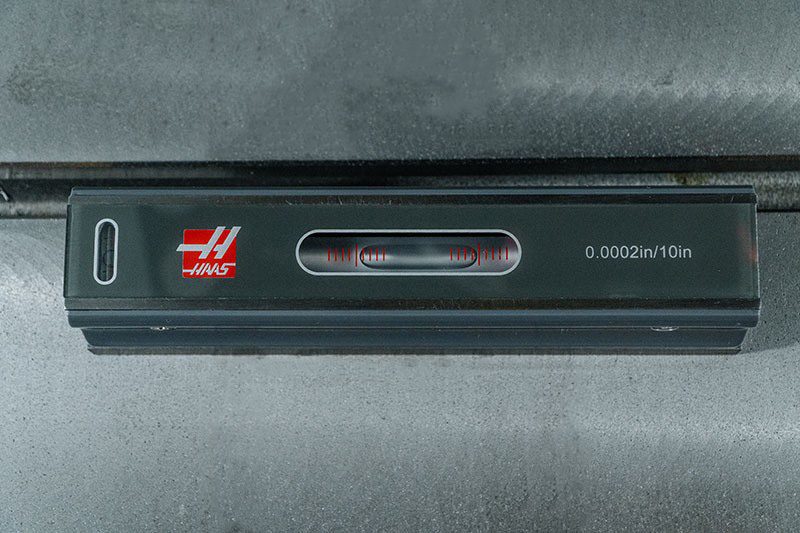
Measuring & Inspection
-
Automation Accessories
-
Shop Support
-
Mill Toolholding
-
Mill Tooling
-
Boring Systems
-
Mill Workholding
-
Lathe Toolholding
-
Lathe Tooling
-
Lathe Workholding
-
Package Kits
-
ER Collets & Chucks
-
Holemaking
-
Threading
-
Broaching
-
Tombstones
-
Manual Chucks For Milling
-
Deburring & Abrasives
-
Tool Presetter & Heat Shrinkers
-
Tool Storage
-
Machine Maintenance
-
Tooling Accessories
-
Apparel & Accessories
 Automation Accessories
 Shop Support
 Mill Toolholding
 Mill Cutting Tools
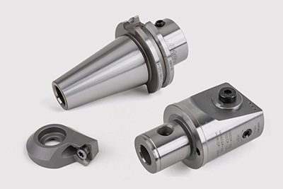 Boring Systems
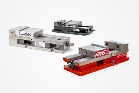 Mill Workholding
 Lathe Toolholding
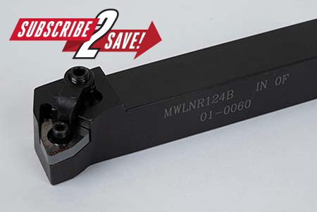 Lathe Cutting Tools
 Lathe Workholding
 Package Kits
 ER Collets & Chucks
 Holemaking
 Threading
 Broaching
 Tombstones & Kits
 Manual Chucks For Milling
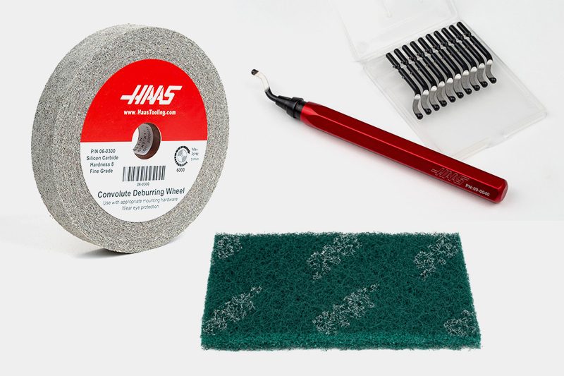 Deburring & Abrasives
 Tool Presetter & Heat Shrinkers
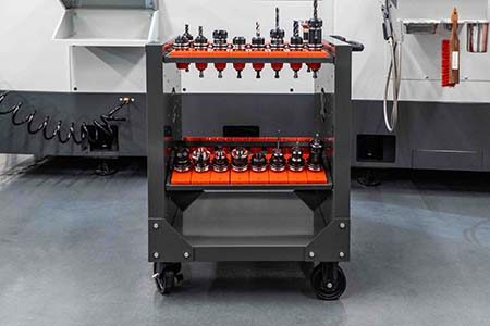 Storage & Handling
 Machine Maintenance
 Tooling Accessories
 Apparel & Accessories
 Measuring & Inspection
 Winner's Circle
Winner's Circle
Winner's Circle
 Clearance
 Today's Hot Deals
-
Haas Service Parts
- Haas Service Parts
-
Automatic Pallet Changer
-
Lathe Turret
-
Tool Changer
-
Chip Management
-
Coolant
-
Counterbalance
-
Electrical Cabinet
-
Enclosure
-
Hydraulics
-
Lubrication
-
Maintenance
-
Pendant
-
Probing
-
Rotary
-
Spindles
-
Tailstock
 Automatic Pallet Changer
 Lathe Turret
 Tool Changer
 Chip Management
 Coolant
 Counterbalance
 Electrical Cabinet
 Enclosure
 Hydraulics
 Lubrication
 Maintenance
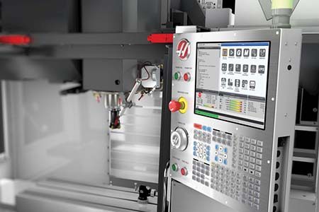 Pendant
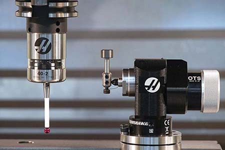 Probing
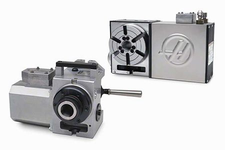 Rotary
 Spindle
 Tailstock