MyHaas Welcome,
!
Haas Tooling Guest Order History MyHaas/HaasConnect Sign In Register Haas Tooling My Account Order History Return History MyHaas/HaasConnect Sign Out Welcome, My Machines Latest Activity My Quotes My Account My Users Sign Out
0
Find Your Distributor
  1. Select Language
    1. English
    2. Deutsch
    3. Español - España
    4. Español - México
    5. Français
    6. Italiano
    7. Português
    8. Český
    9. Dansk
    10. Nederlands
    11. Magyar
    12. Polski
    13. Svenska
    14. Türkçe
    15. 中文
    16. Suomi
    17. Norsk
    18. الإنجليزية
    19. български
    20. Hrvatski
    21. Ελληνικά
    22. Română
    23. Slovenský
    24. Slovenščina
    25. 한국어
    26. 日本語
    27. Українська
  • machines Main Menu
    • Haas Vertical Mills Vertical Mills
      Vertical Mills
      Vertical Mills View All
      • Vertical Mills
      • VF Series
      • Universal Machines
      • VR Series
      • VP-5 Prismatic
      • Pallet-Changing VMCs
      • Mini Mills
      • Mold Machines
      • High-Speed Drill Centers
      • Drill/Tap/ Mill Series
      • Toolroom Mills
      • Compact Mills
      • Gantry Series
      • SR Sheet Routers
      • Extra-Large VMC
      • Double-Column Mills
      • Control Simulator
      • Mill Automatic Parts Loader
      • VMC/UMC Side-Loading Automatic Parts Loader
      • Compact Automatic Parts Loader
    • Product Image Multi-Axis Solutions
      Multi-Axis Solutions
      Multi-Axis Solutions View All
      • Multi-Axis Solutions
      • Y-Axis Lathes
      • 5-Axis Mills
    • Haas Lathes Lathes
      Lathes
      Lathes View All
      • Lathes
      • ST Series
      • Dual-Spindle
      • Box Way Series
      • Toolroom Lathes
      • Chucker Lathe
      • Haas Bar Feeder V2
      • Lathe Automatic Parts Loader
    • Haas Horizontal Mills Horizontal Mills
      Horizontal Mills
      Horizontal Mills View All
      • Horizontal Mills
      • 50-Taper
      • 40-Taper
    • Haas Rotaries & Indexers Rotaries & Indexers
      Rotaries & Indexers
      Rotaries & Indexers View All
      • Rotaries & Indexers
      • Rotary Tables
      • Indexers
      • 5-Axis Rotaries
      • Extra-Large Rotaries
    • Special Series
      Special Series
      Special Series View All
      • Special Series
      • EU_Series_Redirect
    • Product Image Automation Systems
      Automation Systems
      Automation Systems View All
      • Automation Systems
      • Mill Automation
      • Lathe Automation
      • Automation Models
    • Haas Drill Centers Desktop Machines
      Desktop Machines
      Desktop Machines View All
      • Desktop Machines
      • Desktop Mill
      • Desktop Lathe
    • Haas Shop Equipment Shop Equipment
      Shop Equipment
      Shop Equipment View All
      • Shop Equipment
      • Bandsaw
      • Knee Mill
      • Surface Grinder, 2550
      • Surface Grinder, 3063
      • Laser Cutting Machine
    • QUICK LINKS Special Series  Special Series 
      EU SERIES EU SERIES BUILD & PRICE | PRICE LIST BUILD & PRICE | PRICE LIST In-Stock Machines In-Stock Machines WHAT’S NEW WHAT’S NEW YOUR FIRST CNC YOUR FIRST CNC
      SHOPPING TOOLS
      • Build & Price a Haas
      • Price List
      • Available Inventory
      • CNCA Financing
      WANT TO TALK TO SOMEONE?

      A Haas Factory Outlet (HFO) can answer your questions, and walk you through your best options.

      CONTACT YOUR DISTRIBUTOR >
  • Options Main Menu
    • Product Image Spindles
      Spindles
      Spindles View All
      • Spindles
    • Product Image Tool Changers
      Tool Changers
      Tool Changers View All
      • Tool Changers
    • Product Image 4th- | 5th-Axis
      4th- | 5th-Axis
      4th- | 5th-Axis View All
      • 4th- | 5th-Axis
    • Product Image Turrets & Live Tooling
      Turrets & Live Tooling
      Turrets & Live Tooling View All
      • Turrets & Live Tooling
    • Product Image Probing
      Probing
      Probing View All
      • Probing
    • Haas Chip & Coolant Management Chip & Coolant Management
      Chip & Coolant Management
      Chip & Coolant Management View All
      • Chip & Coolant Management
    • The Haas Control The Haas Control
      The Haas Control
      The Haas Control View All
      • The Haas Control
    • Product Image Product Options
      Product Options
      Product Options View All
      • Product Options
    • Product Image Tooling & Fixturing
      Tooling & Fixturing
      Tooling & Fixturing View All
      • Tooling & Fixturing
    • Product Image Workholding
      Workholding
      Workholding View All
      • Workholding
    • Product Image 5-Axis Solutions
      5-Axis Solutions
      5-Axis Solutions View All
      • 5-Axis Solutions
      • 5 Easy Steps to 5-Axis
    • QUICK LINKS Special Series  Special Series 
      EU SERIES EU SERIES BUILD & PRICE | PRICE LIST BUILD & PRICE | PRICE LIST In-Stock Machines In-Stock Machines WHAT’S NEW WHAT’S NEW YOUR FIRST CNC YOUR FIRST CNC
      SHOPPING TOOLS
      • Build & Price a Haas
      • Price List
      • Available Inventory
      • CNCA Financing
      WANT TO TALK TO SOMEONE?

      A Haas Factory Outlet (HFO) can answer your questions, and walk you through your best options.

      CONTACT YOUR DISTRIBUTOR >
  • Why Haas Main Menu
      Discover the Haas Difference
    • Why Haas
    • MyHaas
    • Education Community
    • Industry 4.0
    • Haas Certification
    • Customer Testimonials
  • Service Main Menu
      Welcome to Haas Service
      SERVICE HOME Operator’s Manuals How-To Procedures Troubleshooting Guides Preventive Maintenance Haas Parts Haas Tooling Videos
  • Videos Main Menu
  • Main Menu
    • View All
    • View All
      • Fiber Laser
    • View All
    • View All
      • HTEC Curriculum Support
    • View All
      • Haas 10 kg Cobot Package
      • Cobot Kits
    • View All
    • View All
      • 4 - AUTOMATION SYSTEMS
      • Mill Toolholding
      • Carousel-V2
    • View All
    • View All
    • View All
      • VF-4SS
    • View All
    • QUICK LINKS Special Series  Special Series 
      EU SERIES EU SERIES BUILD & PRICE | PRICE LIST BUILD & PRICE | PRICE LIST In-Stock Machines In-Stock Machines WHAT’S NEW WHAT’S NEW YOUR FIRST CNC YOUR FIRST CNC
      SHOPPING TOOLS
      • Build & Price a Haas
      • Price List
      • Available Inventory
      • CNCA Financing
      WANT TO TALK TO SOMEONE?

      A Haas Factory Outlet (HFO) can answer your questions, and walk you through your best options.

      CONTACT YOUR DISTRIBUTOR >
  • Haas Tooling Main Menu
      Automation Accessories Shop Support Mill Toolholding Mill Cutting Tools Boring Systems Mill Workholding Lathe Toolholding Lathe Cutting Tools Lathe Workholding Package Kits ER Collets & Chucks Holemaking Threading Broaching Tombstones & Kits Manual Chucks For Milling Deburring & Abrasives Tool Presetter & Heat Shrinkers Storage & Handling Machine Maintenance Tooling Accessories Apparel & Accessories Measuring & Inspection Winner's Circle Winner's Circle Clearance Today's Hot Deals
    • Haas Tooling
    • Winner's Circle
      Winner's Circle Shop All
      • WINNERS_CIRCLE-1Y
    • Winner's Circle
      Winner's Circle Shop All
      • WC-1Y-EU
    • Today’s Hot Deals
      Today’s Hot Deals Shop All
      • Mill Toolholding
      • Mill Tooling
      • Measuring & Inspection
      • Boring Systems
      • Mill Workholding
      • Shell Mill Kits
      • Lathe Toolholding
      • Lathe Tooling
      • Lathe Workholding
      • ER Collets & Chucks
      • Holemaking
      • Threading
      • Broaching
      • Tool Storage
      • Apparel & Accessories
    • Clearance
      Clearance Shop All
    • Measuring & Inspection
      Measuring & Inspection Shop All
      • Probe Kits & Accessories
      • Edge & Center Finders
      • Comparative Measuring Gauges
      • Height Gauges
      • Calipers
      • Threaded Plug & Ring Gauges
      • Gauge Blocks
      • Pin Gauges
      • Drop Indicators
      • Dial Test Indicators
      • Bore Gauges
      • Indicator Accessories
      • V Blocks
      • Setup Blocks
      • Depth Measuring
      • Micrometers
      • Micrometer Accessories
      • Micrometer Kits
      • Bore Gauge Kits
      • Starter Kits
      • Indicator Kits
      • Caliper Kits
      • Toolholder Check Station
      • Height Setters
      • Coordinate Measuring Machines
    • Automation Accessories
      Automation Accessories Shop All
      • Cobot Kits
      • Cobot Kits
      • Protective Barriers
      • Grippers
      • Robot Cell Accessories
    • Shop Support
      Shop Support Shop All
      • Air Compressors
      • Laser Marking Machines
      • Bandsaw Blades
      • Bandsaw Accessories
      • Surface Grinding Wheels
      • Shop Equipment Accessories
    • Mill Toolholding
      Mill Toolholding Shop All
      • End Mill Holders
      • Shell Mill Holders
      • Shrink Fit Holders
      • ER Collet Chucks
      • Milling Chucks & Collets
      • NC Drilling Chucks
      • Pull Studs / Retention Knobs
      • Rotary Tool Holder & Tool Chuck Kits
      • Hydraulic Milling Chucks & Collets
      • Toolholder Attachments & Wrenches
      • Mill Broaching Holders
    • Mill Tooling
      Mill Tooling Shop All
      • Shell Mill Bodies
      • Milling Inserts
      • End Mills
      • Chamfer Mills & Inserts
      • Indexable End Mill Bodies
      • Ball End Mills
      • Chamfer End Mills
      • Roughing End Mills
      • Indexable Ball End Mills & Inserts
      • Shell Mill Kits
      • Chamfer Mill Kits
      • Indexable End Mill Kits
      • Dovetail Cutters
      • Indexable Dovetail Cutters
      • Engraving End Mills
      • Rotary Burrs / Die Grinding Bits
      • Keyseat Cutters
      • Corner Rounding End Mills
      • Slot Mill Bodies
      • CNC Router Bits For Wood
    • Boring Systems
      Boring Systems Shop All
      • Boring Heads & Cartridges
      • Boring Holders & Extensions
    • Mill Workholding
      Mill Workholding Shop All
      • Fixed-Jaw Vises
      • Self-Centering Vises
      • Adapter Plates
      • Vise Jaws
      • Vise Mounts & Fixtures
      • Vise Kits
      • Vise Parallels
      • Rotary Vise Kits
      • Fixture Clamps & Rails
      • Automated Workholding Kits
      • Tooling Fixture Subplates
      • Toolmakers' Vises
      • Clamp Force Gauges
      • Collet Fixtures
      • Angle Plates
    • Lathe Toolholding
      Lathe Toolholding Shop All
      • TL & CL Static Turning Holders
      • BOT Static Turning Holders
      • BMT Static Turning Holders
      • Live / Driven Turning Holders
      • Turning Holder Reduction Sleeves / Bushings
      • VDI Static Turning Holders
      • Turning Holder Accessories
    • Lathe Tooling
      Lathe Tooling Shop All
      • Cut-Off Tool Blocks & Blades
      • Cut-Off Tooling Kits
      • Turning Inserts
      • Grooving & Cut-Off Tools
      • Internal (ID) Grooving & Threading Tools
      • Threading Inserts
      • Threading Tools
      • Boring Bars / Internal (ID) Turning Tools
      • External (OD) Turning Tools
      • Cermet Turning Inserts
      • CBN Turning Inserts
      • Haas Notch Grooving & Threading Inserts
      • Haas Notch Grooving & Threading Tools
      • Micro Turning Tools
      • Desktop Lathe Tools
    • Lathe Workholding
      Lathe Workholding Shop All
      • Live Centers
      • Spindle Reduction Sleeves / Liners
      • Quick-Change Collets
      • Quick-Change Collet Chucks
      • 5C Collets
      • 5C Collet Sets
      • Lathe Jaw Boring Rings
      • Lathe Jaws
      • Bar Pullers
      • Scroll Chucks
      • Guide Pins
      • Collet Accessories
    • Package Kits
      Package Kits Shop All
      • Chip Clearing Fan Kits
      • Cutting Tool Kits
      • Indexable End Mill Kits
      • Cut-Off Tool Block & Blade Kits
      • Drill & Tap Kits
      • Indexable Drilling Kits
      • Shell Mill Kits
      • Chamfer Mill Kits
      • Rotary Tool Holder & Tool Chuck Kits
      • Lathe Starter Kits
      • Workholding Kits
      • Rotary Vise Kits
      • Vise Kits
      • 3-Jaw Chuck Kits for Mills
      • Tombstone Kits
      • Reduction Sleeve Kits
      • Automated Workholding Kits
      • Measuring & Inspection Kits
      • Starter Kits
      • Bore Gauge Kits
      • Caliper Kits
      • Indicator Kits
      • Micrometer Kits
    • ER Collets & Chucks
      ER Collets & Chucks Shop All
      • ER Straight-Bore Collets
      • ER Sealed Collets
      • ER Tap Collets
      • ER Collet Sets & Accessories
      • ER Collet Chucks
      • Straight Shank ER Collet Chucks
      • Straight Shank Keyless NC Drilling Chucks
    • Holemaking
      Holemaking Shop All
      • Carbide Drills
      • Indexable Drill Bodies
      • Indexable Drill Inserts
      • Modular Drill Bodies
      • Modular Drill Heads
      • Cobalt Drills & Sets
      • Center Drills
      • Reamers
      • Indexable Drilling Kits
      • Spot Drills
      • Spade Drill Bodies
      • Spade Drill Inserts
      • Countersinks
    • Threading
      Threading Shop All
      • Taps
      • Threading Inserts
      • Threading Tools
      • Thread Mills
      • Pipe Taps
      • Drill Tap Kits
    • Broaching
      Broaching Shop All
      • Broaching Tools
      • Broaching Inserts
    • Tombstones
      Tombstones Shop All
      • Tombstones
      • Tombstone Kits
      • Vise Cluster Towers
    • Manual Chucks For Milling
      Manual Chucks For Milling Shop All
      • 3-Jaw Chucks & Mounts for Mills
    • Deburring & Abrasives
      Deburring & Abrasives Shop All
      • Abrasive Pads
      • Deburr Tools
      • Deburr Wheels
      • Abrasive Sheets & Rolls
      • Sharpening / Lapping Stones
    • Tool Presetter & Heat Shrinkers
      Tool Presetter & Heat Shrinkers Shop All
      • Tool Presetting Machines
      • Shrink Fit Machines
    • Tool Storage
      Tool Storage Shop All
      • Tool Carts
      • Tool Tray
      • Tool Bags
    • Machine Maintenance
      Machine Maintenance Shop All
      • Spindle Test Bars
      • Levels
      • Refractometers
      • Machine Additives & Supplies
      • Machine Accessories
      • Machine Maintenance Kits
    • Tooling Accessories
      Tooling Accessories Shop All
      • Spindle & Toolholder Taper Cleaners
      • Haas Shop Lift
      • Toolholder Fixtures
      • CNC Chip Clearing Fans
      • Hammers & Mallets
      • Anti-Fatigue Mats
      • Layout Tools
      • Wrenches
      • Magnetic Tools
      • Torque Screwdrivers
      • Hand Cutting Tools
      • Shop Stools
      • Lifting Magnets
      • Safety Apparel
      • Cutting Tool Sharpeners
    • Apparel & Accessories
      Apparel & Accessories Shop All
      • Accessories
      • Apparel
    • HAAS TOOLING QUICK LINKS
      NEW PRODUCTS NEW PRODUCTS NEW PRODUCTS NEW PRODUCTS
      MOST POPULAR MOST POPULAR
      TOOLING PROMOS TOOLING PROMOS
      FINANCING & OPEN TERMS FINANCING & OPEN TERMS PAY BY INVOICE PAY BY INVOICE
      FAQs FAQs
      KITS CREATED FOR YOU KITS CREATED FOR YOU
  • Haas Service Parts Main Menu
      Automatic Pallet Changer Lathe Turret Tool Changer Chip Management Coolant Counterbalance Electrical Cabinet Enclosure Hydraulics Lubrication Maintenance Pendant Probing Rotary Spindle Tailstock
    • Haas Service Parts
    • Automatic Pallet Changer
      Automatic Pallet Changer Shop All
      • HMC - Automatic Pallet Changer
      • VMC - Automatic Pallet Changer
    • Lathe Turret
      Lathe Turret Shop All
      • Lathe - Turret
      • Live Tooling
    • Tool Changer
      Tool Changer Shop All
      • Side Mount
      • Umbrella
    • Chip Management
      Chip Management Shop All
      • Multi Auger
      • Single Auger
    • Coolant
      Coolant Shop All
      • Auxiliary Filter
      • HPC-300 (Lathe)
      • HPC-1000 (Lathe)
      • Oil Skimmer
      • Standard Coolant
      • TSC-300 (Mill)
      • TSC-1000 (Mill)
      • Coolant Refill
      • Loc-Line
    • Counterbalance
      Counterbalance Shop All
      • Charge & Discharge Hose
    • Electrical Cabinet
      Electrical Cabinet Shop All
      • Fans
      • Filters
      • Upgrade Kits
    • Enclosure
      Enclosure Shop All
      • Accessories
      • Air Nozzle
      • Decals
      • Door Bumpers
      • Lighting
      • Windows, Gaskets, & Weather Strip
      • Chip & Coolant Management
    • Hydraulics
      Hydraulics Shop All
      • Filters
      • Gauges
      • Heat Exchanger
      • Hoses
    • Lubrication
      Lubrication Shop All
      • Bijur Mechanical Lubrication
      • Minimum Lubrication
    • Maintenance
      Maintenance Shop All
      • Grease, Oil, & Sealants
    • Pendant
      Pendant Shop All
      • Floppy Disk & USB
      • Keypad
      • Keys
      • Lens
      • Gaskets & Seals
    • Probing
      Probing Shop All
      • Mill Probing
      • Lathe Tool Presetter
    • Rotary
      Rotary Shop All
      • Rotary Gaskets & Seals
    • Spindles
      Spindles Shop All
      • Couplings
      • Gaskets & Seals
      • Spindle Motor Drive
      • Gearbox Drive
      • Tool Release Piston
    • Tailstock
      Tailstock Shop All
      • Handles
×

Search Results

Web Pages

Images

    • <
    • 1
    • >
Use the up and down arrows to select a result. Press enter to go to the selected search result. Touch device users can use touch and swipe gestures.
MyHaas Welcome,
!
Haas Tooling Guest Order History MyHaas/HaasConnect Sign In Register Haas Tooling My Account Order History Return History MyHaas/HaasConnect Sign Out Welcome, My Machines Latest Activity My Quotes My Account My Users Sign Out
0
Find Your Distributor
  1. Select Language
    1. English
    2. Deutsch
    3. Español - España
    4. Español - México
    5. Français
    6. Italiano
    7. Português
    8. Český
    9. Dansk
    10. Nederlands
    11. Magyar
    12. Polski
    13. Svenska
    14. Türkçe
    15. 中文
    16. Suomi
    17. Norsk
    18. الإنجليزية
    19. български
    20. Hrvatski
    21. Ελληνικά
    22. Română
    23. Slovenský
    24. Slovenščina
    25. 한국어
    26. 日本語
    27. Українська
×

Search Results

Web Pages

Images

    • <
    • 1
    • >

2 - APL - Installation

Haas Automatic Parts Loader - Service Manual


  • 1 - APL - Introduction
  • 2 - APL - Installation
  • 3 - APL - Operation
  • 4 - APL - AU-Axis
  • 5 - APL - AV-Axis
  • 6 - APL - Fence Installation
  • 7 - APL - Maintenance
  • 8 - APL - Troubleshooting
  • 9 - APL - Light Curtain

Go To :

  • 2.1 Mill - APL (Front Load)
  • 2.2 Lathe - APL
  • 2.3 UMC - APL
  • 2.4 Compact APL

2.1 Mill - APL

Recently Updated

Haas Automatic Parts Loader (APL) - Mill - Installation


AD0455

Revision A - 04/2025

Introduction

This document explains how to assemble and install the Haas Automatic Parts Loader (APL) for a VMC machine.

Machine Requirements:

  • VF-1/2 & VM-2 Built 4-1-2019 and later
  • Haas Autodoor (See machine requirements for CAN Auto Door)
  • Remote Jog Handle - Touch
  • I/O board updated to 34-349xB or later
  • I/O PCB HINGE DOOR. 93-1000297 I/O DOOR ASSY HINGED
  • NGC/Software Version 100.19.000.1100 or greater
  • SMTC 30 or 50 Pocket
  • Check the Layout Drawing document for Machine Specifications

Note: The automatic vise is not included with the mill APL. It must be ordered as an additional option.

Note: Before installing the APL make sure that the mill is leveled and the distance from the floor to the casting is 3 inches.

APL's that are purchased separate from the machine need to order the field install automation parameters kit that corresponds to how the APL will be used on the machine.

Important: This also applies when the APL is being moved from one machine to another. The machine that the APL is moving to needs to purchase one of the kits below in order to have the correct configuration.

After the kit is purchased, the configuration for needs to be re-uploaded to the machine from HBC.

Field Install Kit Kit Description

93-1000997 - Front Automation Safety Parameter Only

or

93-1000996 - Side Automation Safety Parameter Only

Front Loading APL Safety Parameter

or

Side Loading APL Safety Parameter

 Important: HE machines with an autodoor that are ordered with a robot or APL will not come with an edge sensor because these automation options come with a fence. If the machine is going to be ran without the automation option that has the fence, you will need to order and install an edge sensor for the machine. Reference the applicable edge sensor procedures for the correct part number to order:

  • Mill Edge Sensor Install
  • Lathe Edge Sensor Install

Prepare the Mill

1

Complete the following on both sides of the door:

  • Remove the autodoor motor cover [1]
  • Remove the autodoor motor assembly [2]
  • Install the new proximity switch bracket [3] to the existing proximity switch block [5]
  • Install the door always open proximity switch [4] to the bracket [3]

2

For both doors, continued:
 
  • Install drill guide [2] for the door open flag [1]
  • Drill and tap 2x 10-32 holes through the sheet metal of the door
    • Drill size: #21 or 5/32"
    • Tap 10-32 NF
  • Remove the template and install the door open flag with 2x flat head cap screws
  • Re-install the autodoor motor assembly, bracket, and cover
  • Use provided shims to set the height between the proximity switch and the door open flag

3

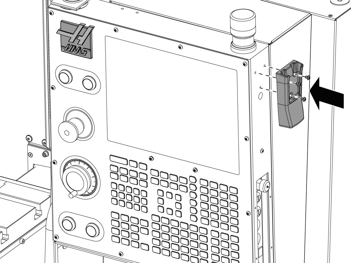
  • Move the Remote Jog Handle (RJH) to the opposite side of the control pendant

4

  • Move the air gun hose mount [1] to the opposite side of the tool rack
  • Drill holes in the tool rack for the 1/4"-20 screws
    • Use a  H (17/64") drill to make clearance holes 

Align APL to the Mill

1

  • Bring the APL approximately 35 inches (89 centimeters) from the front of the machine - measure from the APL pillar to the seam between the sheet metal panels on the front of the machine
  • Remove the back panel shipping bracket [1]
  • Secure the back panel [2] to the support bracket [4]. Leave screws loose
  • Maneuver the APL until you can attach panel [2] to [3]
  • Tighten all screws

2

  • Turn the air supply OFF
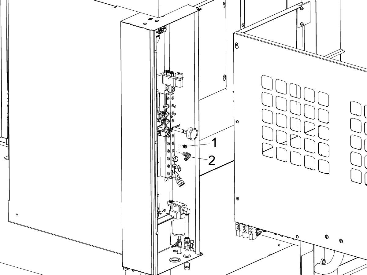
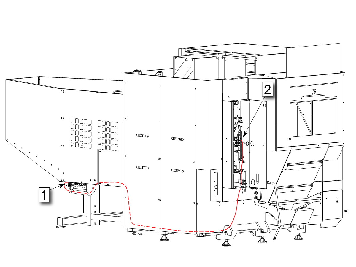
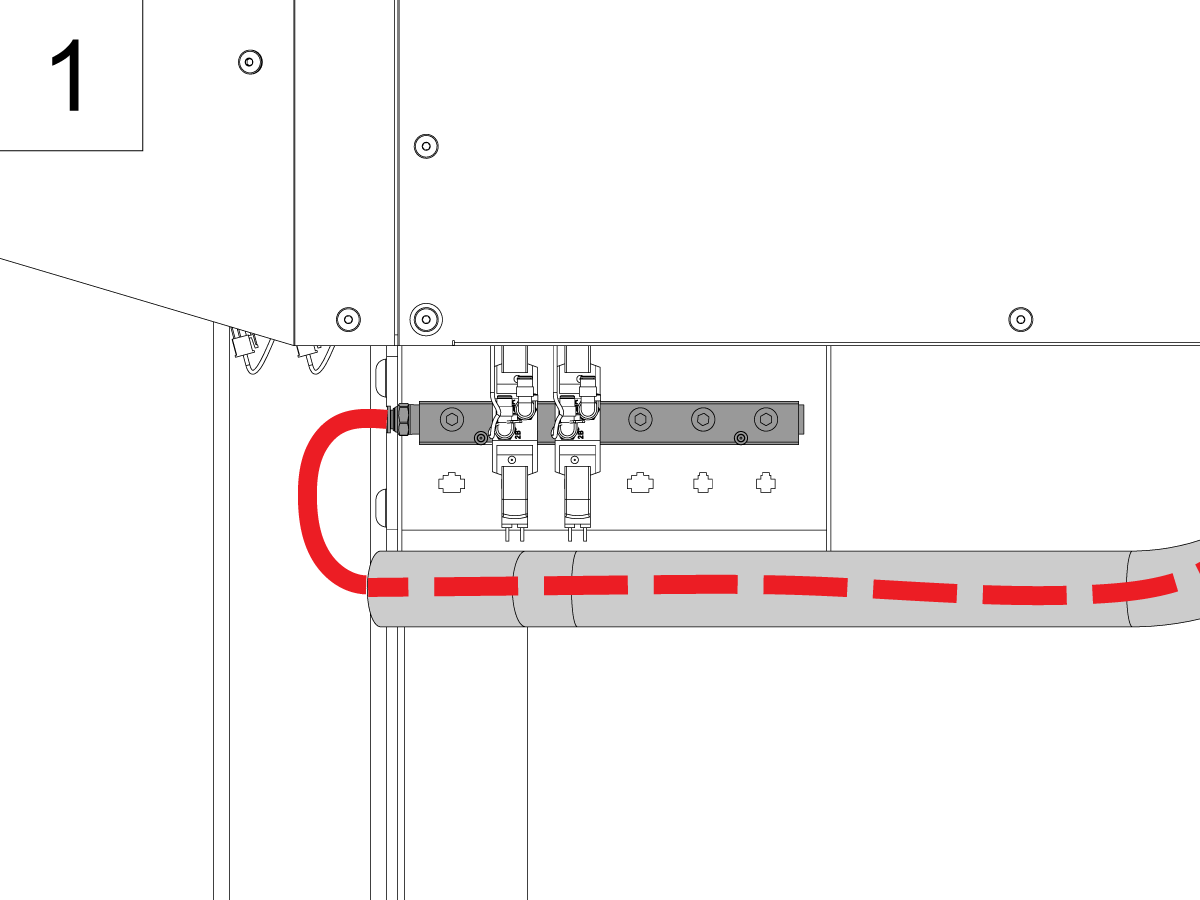
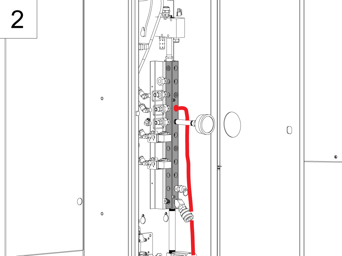
  • Inside the CALM cabinet, remove the NPT plug [1] from one of the CALM manifold ports and install the push to connect fitting
  • Route the air line from the APL solenoid rack to the CALM cabinet and connect it to the fitting

Level the APL

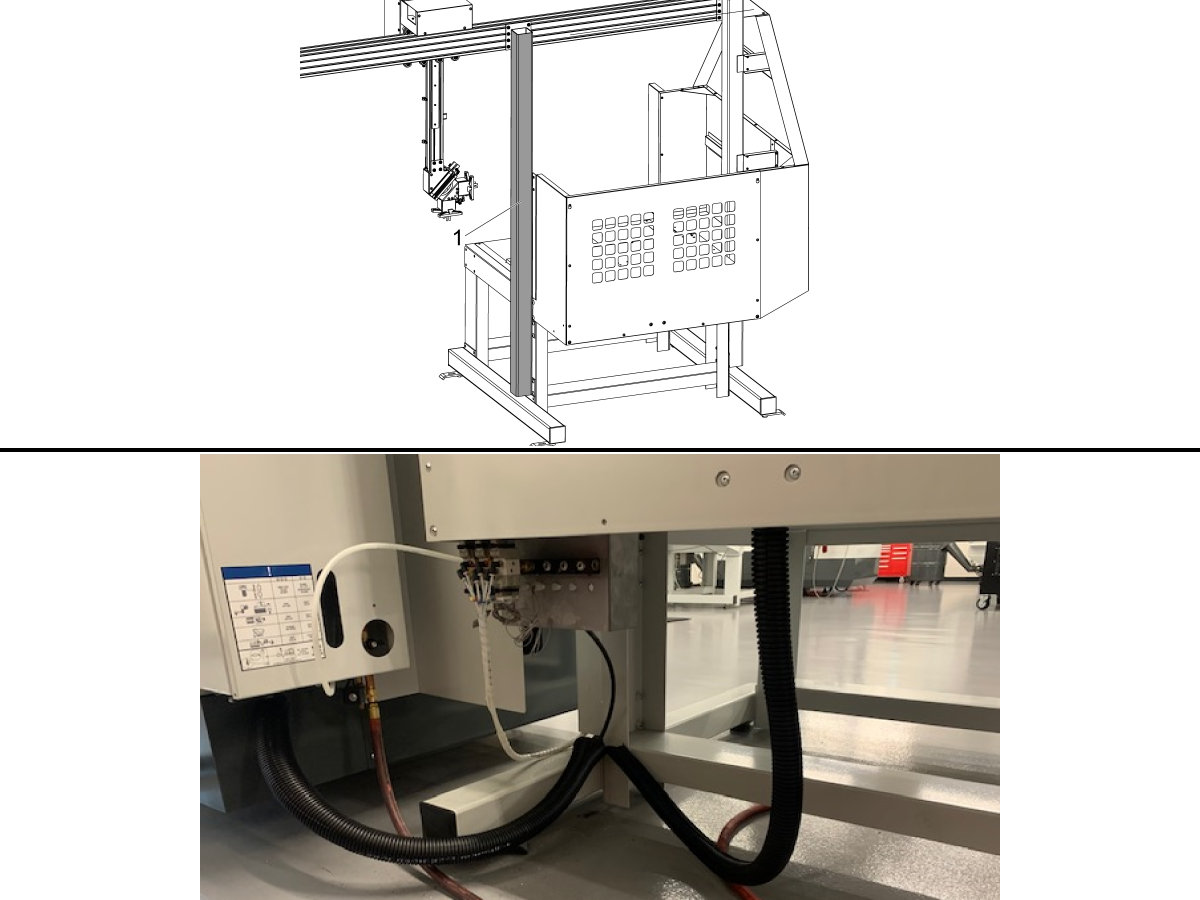
1

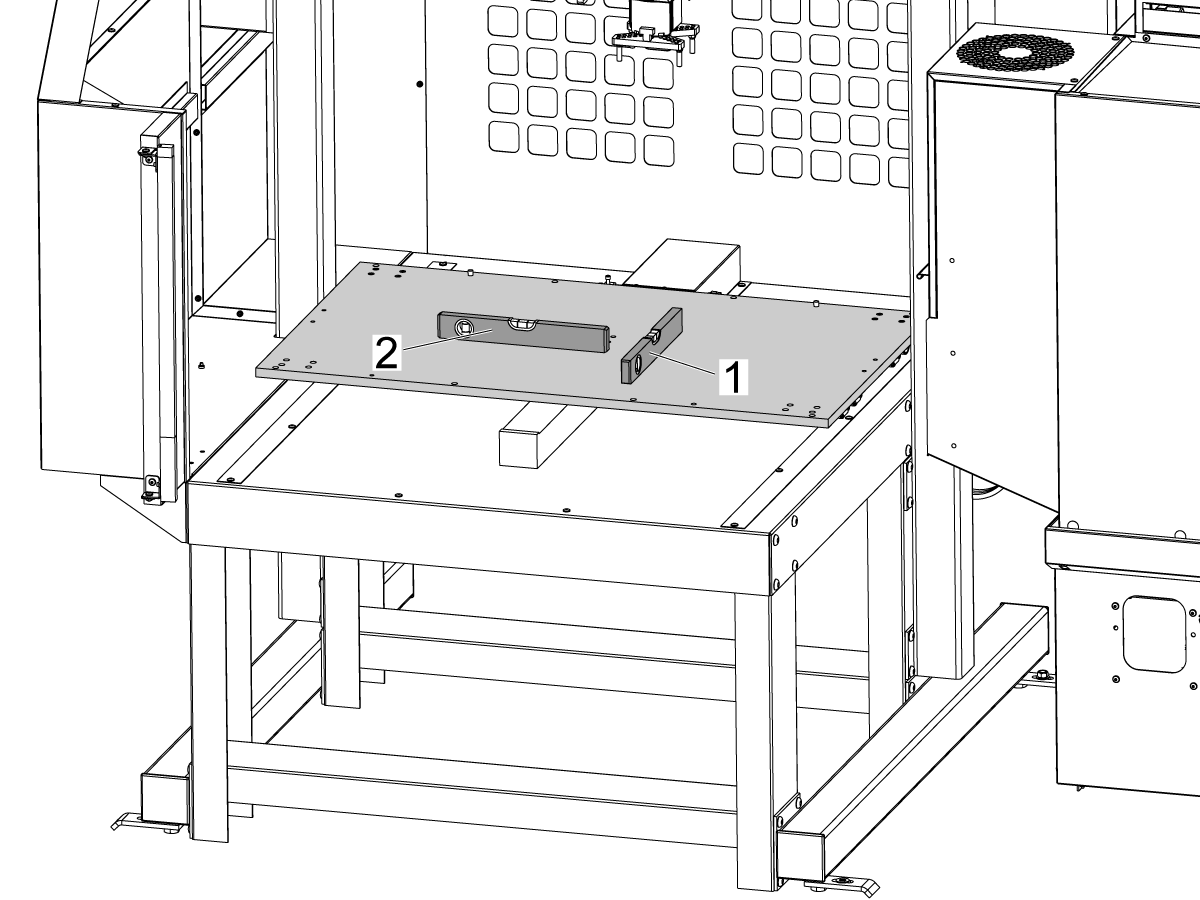
  • Level the APL base with the bubble level on top of the APL table
  • Use the leveling screws at the bottom of the APL base to level the APL front to back [1] and side to side [2]
  • When done with leveling make sure that all four leveling screws make contact with the floor
  • Place the level on top of the horizontal beam [3]
  • Loosen the bolts that secure the beam to the pillars
  • Lift or lower the right side [2] of the horizontal beam until it is leveled
  • Tighten the bolts that secure the horizontal beam to the pillars

Shipping Brackets

1

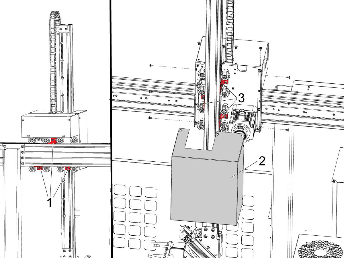
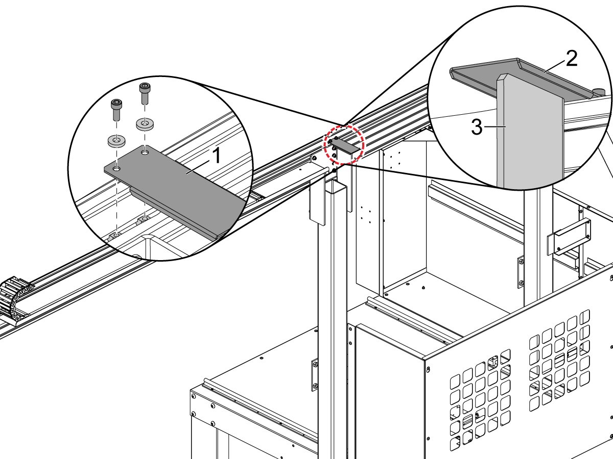
  • Remove the APL arm shipping bracket [1]

2

  • Remove the table shipping brackets [1], [2]

3

  • Remove the AW axes sheet metal shroud [2]
  • Remove the AU and AW axes shipping brackets [1]

Enable the APL

1

WARNING: Perform this step before connecting electrical APL components to the machine.

Note: The control needs to be in Service Mode to access the Factory Settings menu

  • E-STOP the machine
  • Change parameter 2191 LIGHT CURTAIN TYPE to LC_TYPE_1
  • Change parameter 2195 ENABLE RIGHT DOOR FULLY OPEN SWITCH to TRUE
  • Change parameter 2196 ENABLE LEFT DOOR FULLY OPEN SWITCH to TRUE
  • Set the setting 372 PARTS LOADER TYPE to TYPE 2 MILL APL
  • Set the setting 375 APL GRIPPER TYPE to Dual Gripper
  • Set the Setting 376 LIGHT CURTAIN ENABLE to ON
  • Keep the E-STOP depressed and power the machine OFF


Electrical Installation

1

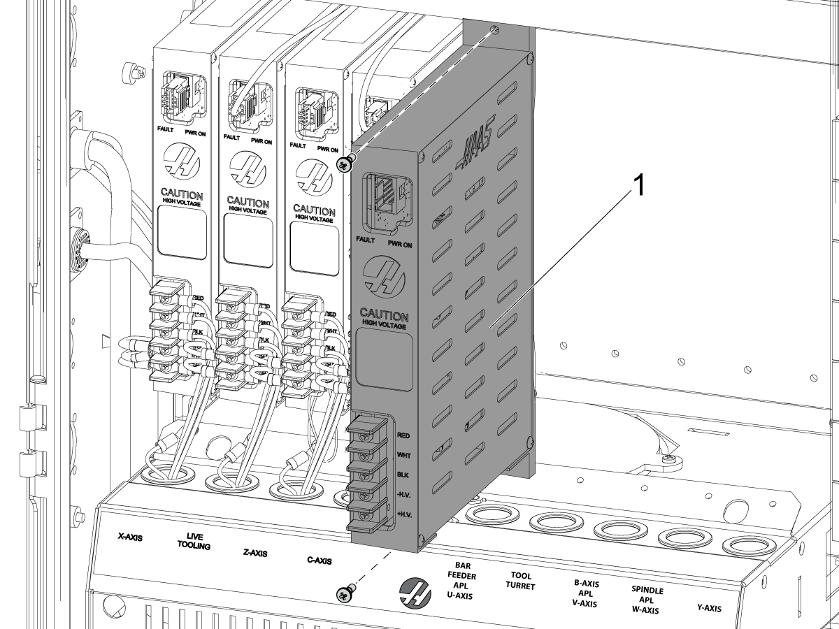
  • Install the AU, AV and AW axes amplifiers in the respect with the decal labels on the amplifier fan bracket 

Note: AU axis amplifier [1] shown on the picture


2

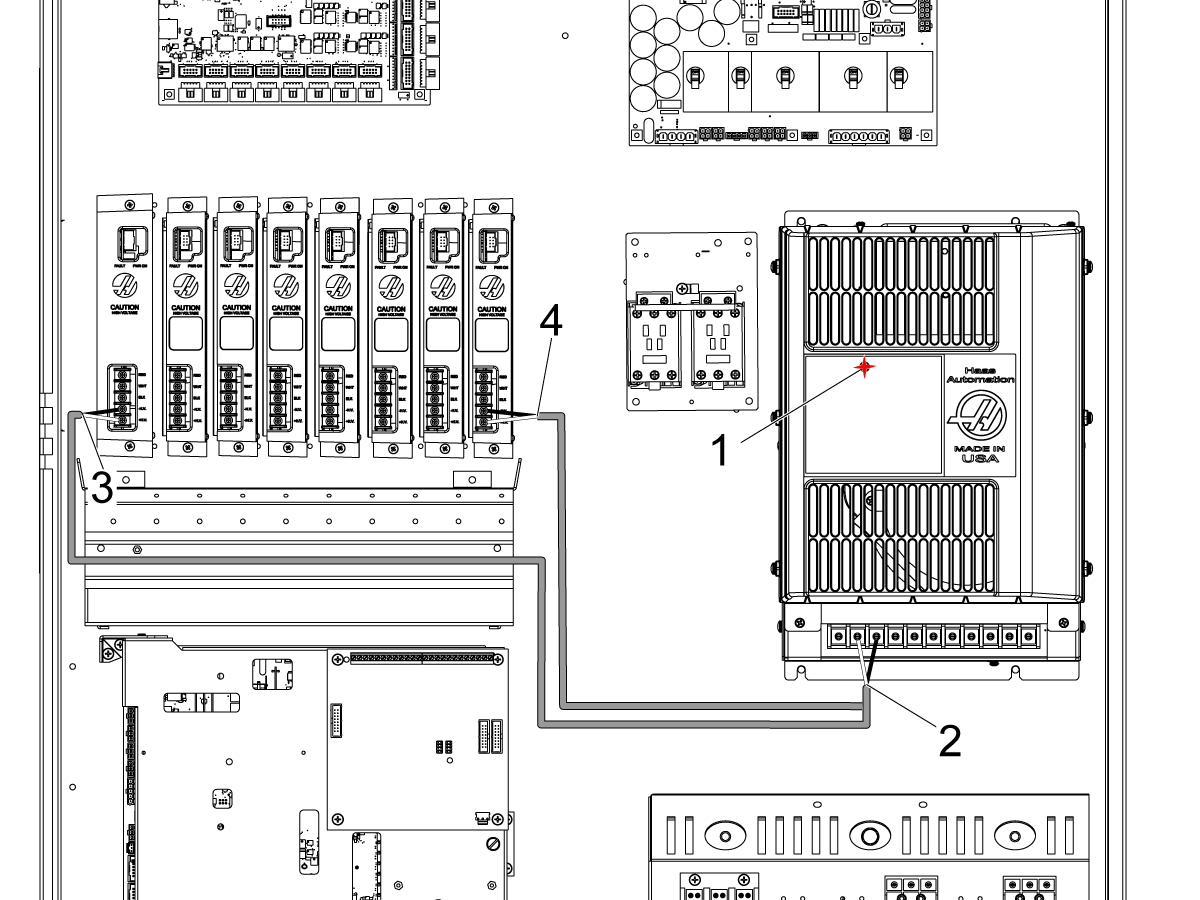
  • If the machine was built with the single lead DC buss cable (33-04901B) you will need to replace it with the dual lead DC BUS cable (33-0052C) provided with the kit
  • Before working on this cable, power the machine OFF and allow the Vector Drive capacitors to discharge until the red light [1] on the Vector Drive is OFF
  • Remove the old cable that supplies DC voltage from the Vector Drive terminals 2 and 3 to the amplifiers
  • Install the new dual lead DC BUS cable (33-0052C) as follows:
    • Connect the end with the ring terminals [2] to the terminal 2 and 3 on the Vector Drive:
      • The white lead that is labeled TB2 "+" to the terminal 2
      • The black lead that is labeled TB3 "-" to the terminal 3
  • Route the longer cable through the fan bracket under the amplifiers and connect it to the "+" H.V. and the "-" H.V. terminals on the left most servo amplifier [3] as labeled
  • Connect the remaining cable to the "+" H.V. and the "-" H.V. terminals on the right most servo amplifier [4] as labeled


3

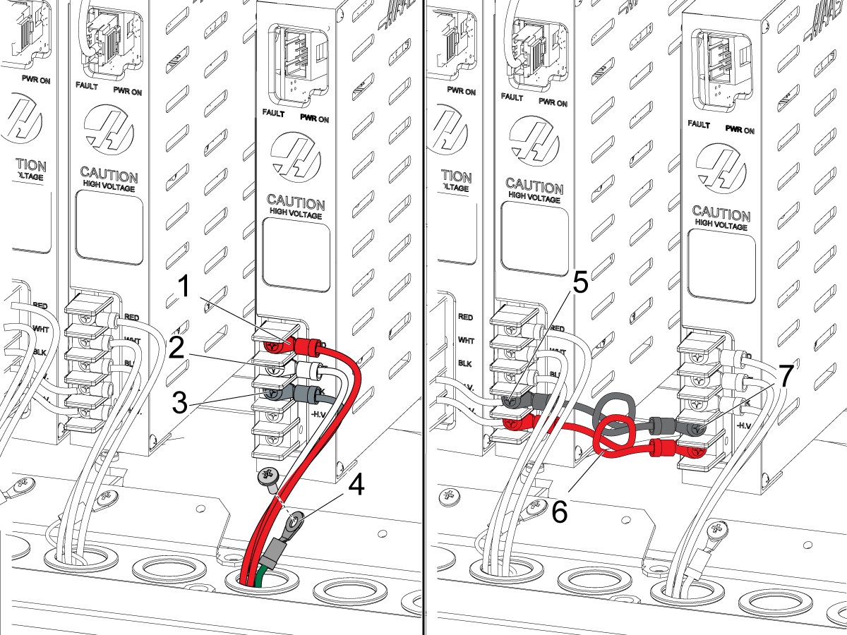
  • Route the AU, AV and AW axes power cables through the opening on the bottom of the control cabinet
  • Connect the power cable leads to the high voltage terminals Note: The AV axis power cable leads are labeled PH-A, PH-B and PH-C due to a different color scheme. Connect as follows::
    • red to RED [1]
    • white to WHT [2]
    • black to BLK [3]
    • PH-A to RED
    • PH-B to WHT
    • PH-C to BLK
  • Connect the ground wire [4] to the bracket for the amplifier fan
  • Find the high-voltage terminals [5] on the nearest amplifier
  • Find the high-voltage terminals [7] on the amplifier
  • Install the jumpers [6] from the installation kit between these terminals
  • Connect the black wire to -H.V. Connect the red wire to +H.V.

4

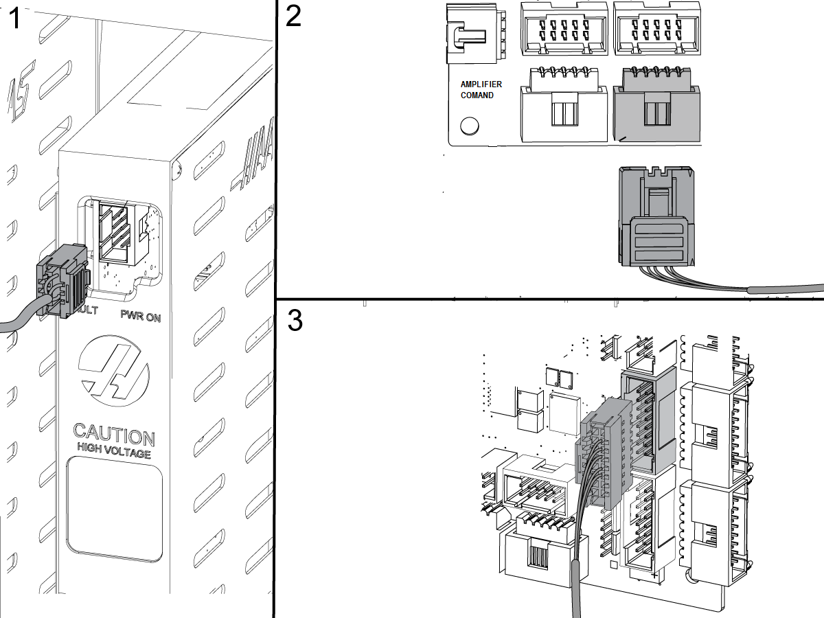
  • Connect the current command cables to the connector near the top of the each amplifier [1]
  • Connect the other ends of the cables to the AMPLIFIER COMMAND outputs on the NGC PCB [2] as follows:
    • AU axis to the output 13
    • AV axis to the output 15
    • AW axis to the output 16
  • Route the U, V and W axes encoder cables through the opening on the bottom of the control cabinet and connect them to the ENCODER inputs on the NGC PCB [3] as follows:
    • AU axis to the input 13
    • AV axis to the input 15
    • AW axis to the input 16
  • Route the AW axis brake cable into the control cabinet and connect it to P3/4/5 on the SIO

5

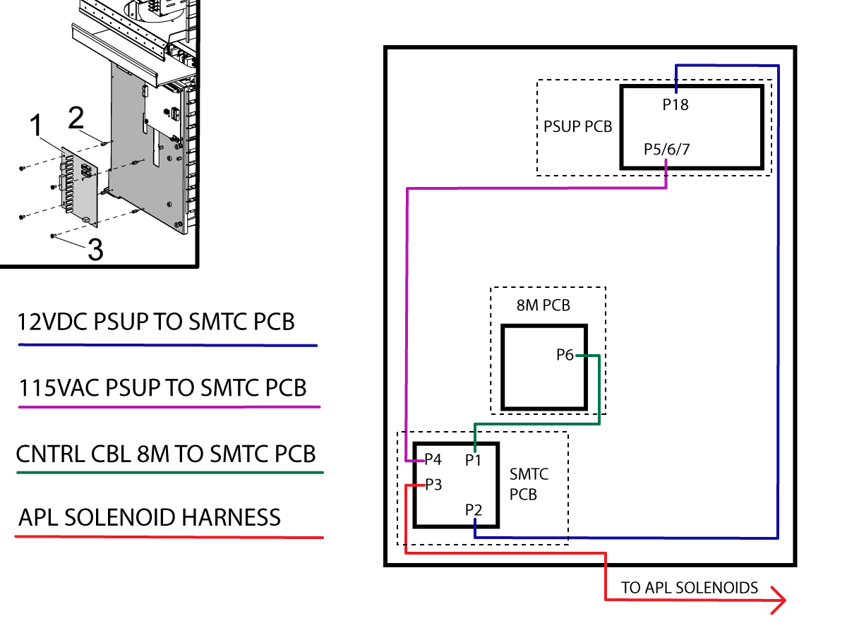
Install the SMTC PCB [1] onto the SIO door using the standoffs [2] and the screws [3].

Interconnect the SMTC PCB cables as shown on the diagram.

If the machine has a Smart CAN auto door, plug cable 33-1518 into P15 on the SIO board. 

I/O PCB Hinge Door - Installation

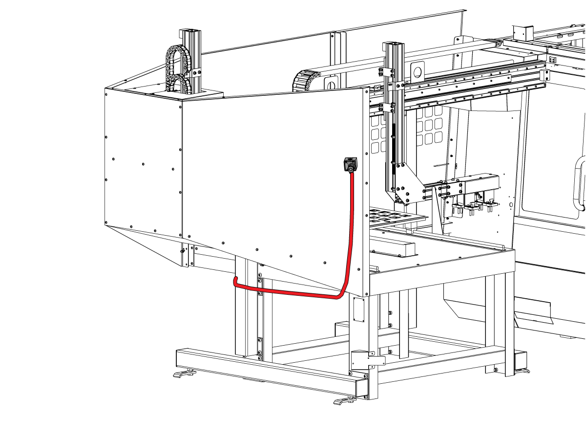
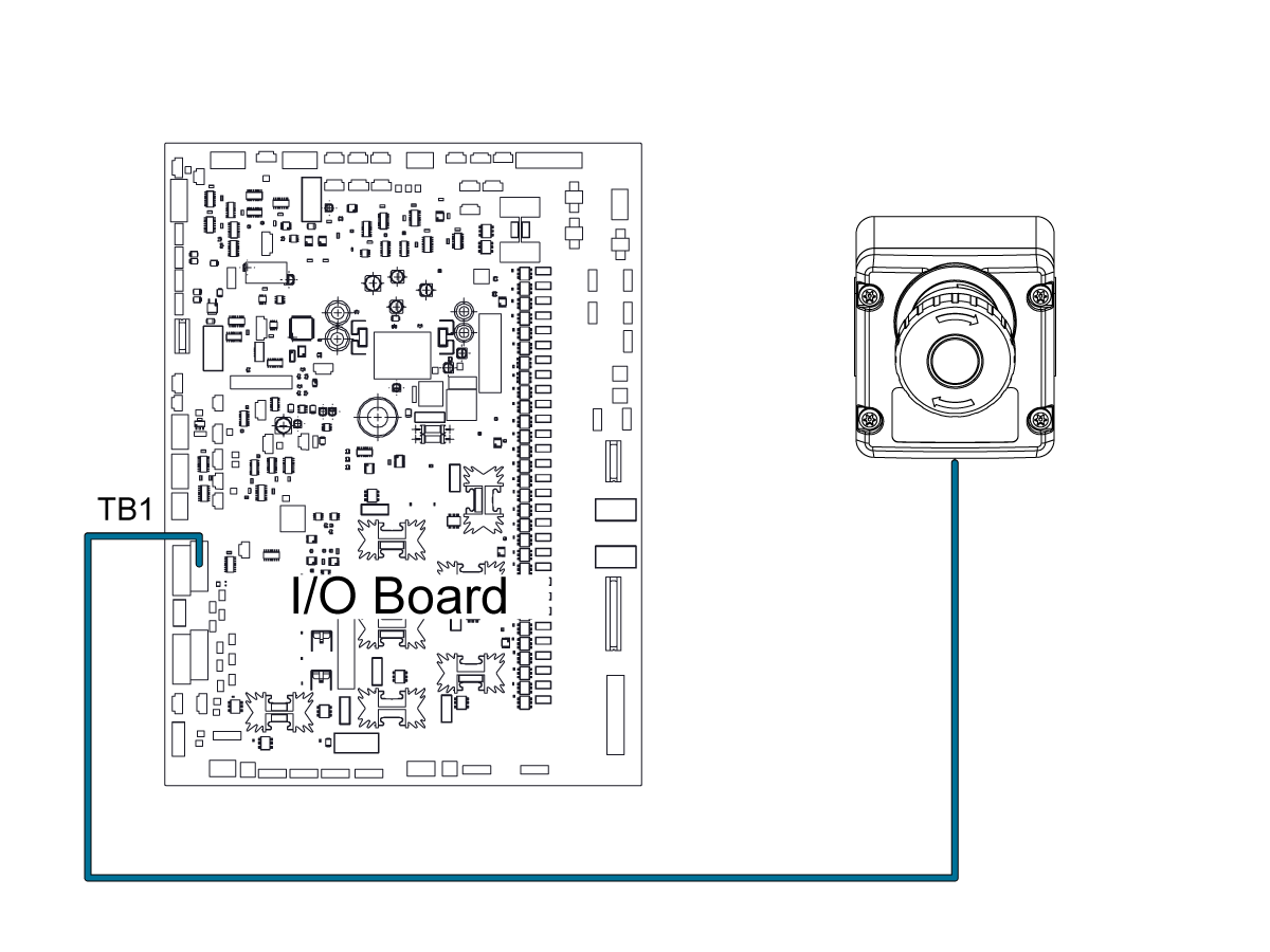
APL E-Stop - Install

1

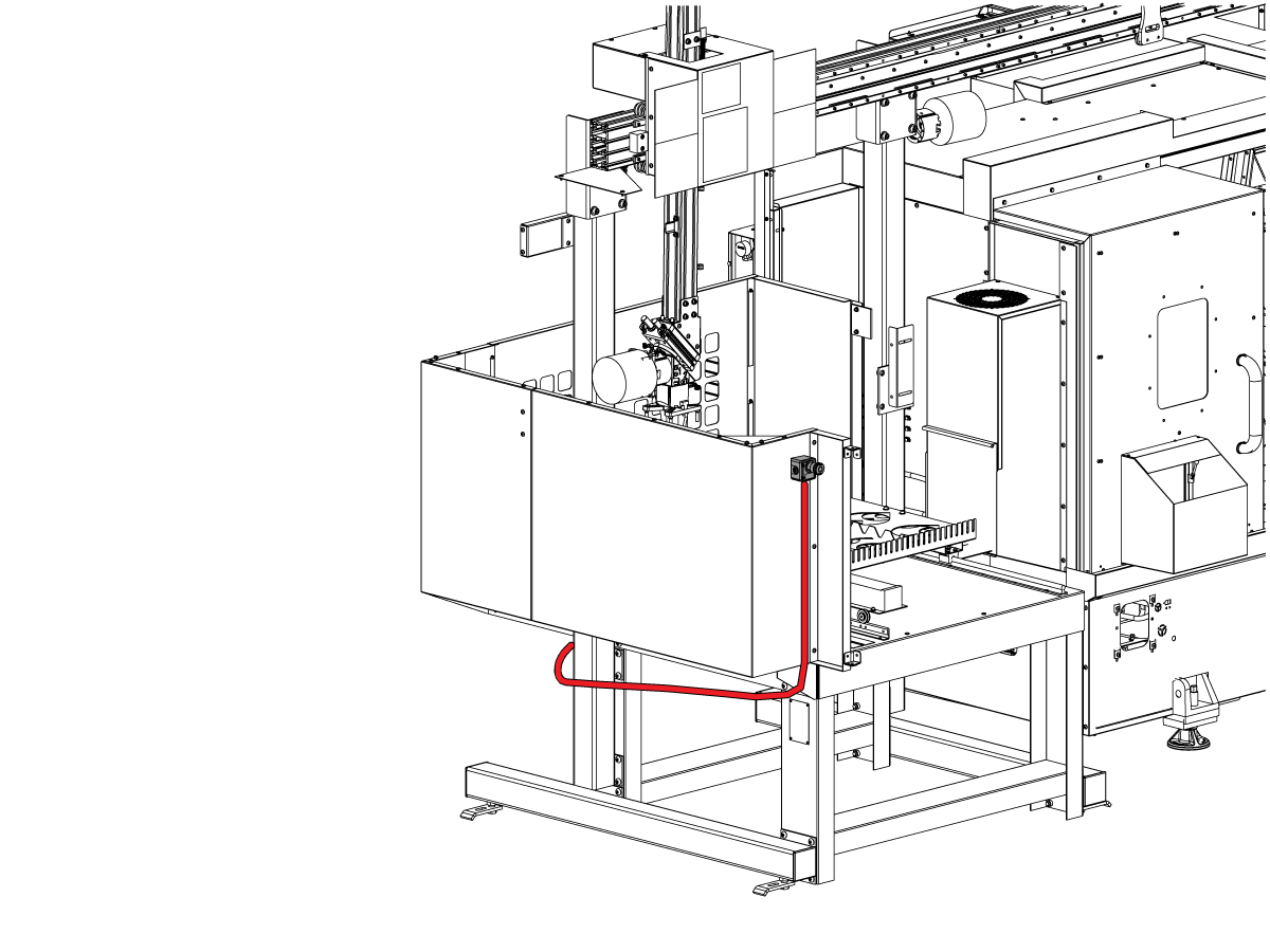
Attach the APL E-Stop as shown and route the cable along the bottom so that it groups up with the other cables that route to the control cabinet.

2

Connect the APL E-Stop button wire to TB1 on the I/O Board.

Remove jumper from JP1 on the I/O PCB.

Change factory setting: 1278 [1278]: Robot Ready E-Stop Enabled to True

Light Curtain Installation

1

 NOTE: For Machines with light curtain perform this section. 
  • Place the machine side light curtain mount flush with the bottom and side of the door opening as shown in the picture
  • Mark off hole pattern
  • Drill holes using a #14 drill (3/16")
  • Install light curtain mount and self-tapping screws [1]

2

  • Remove the tool tray plastic insert [1] to gain access to the screw to remove the tool tray
  • Remove the tool tray [2]
  • Place two screws into the bracket [3]
  • Install 4x 40-1985 sheet metal screws [4] leave screws loose to aid with alignment of the APL. Tighten once APL is aligned.
  • Re-install the tool tray in addition to the tool tray spacer included in the install kit

3

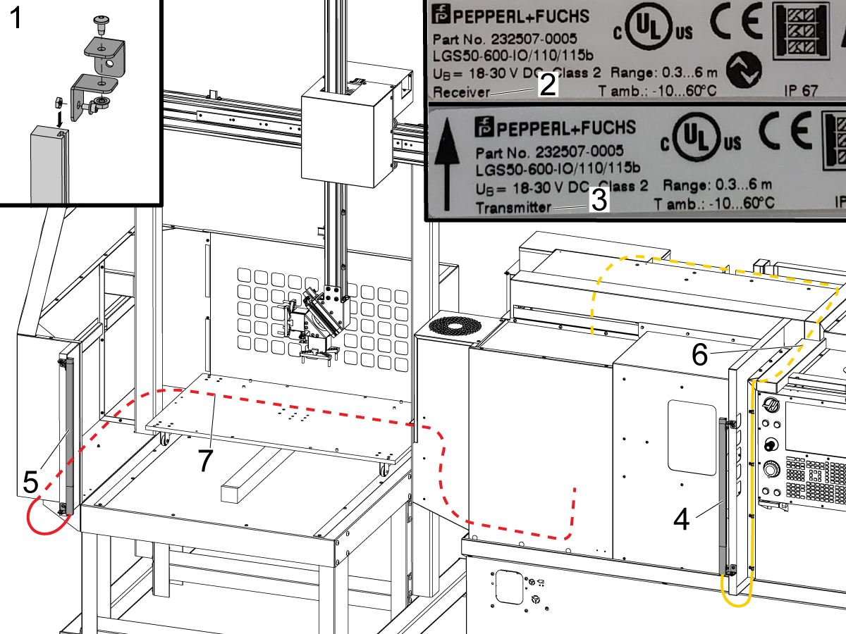
  • Assemble the light curtain brackets [1]
  • Note: The light curtain kit contains the transmitter and the receiver. You can identify these by the sticker on the side of the housing. It is labeled "RECEIVER" [2] and "TRANSMITTER" [3]
  • When installing the light curtains make sure that the end with the cable connection is on the bottom
  • Install the light curtain receiver [4] on the mill side
  • Install the light curtain transmitter on the APL side on the bracket next to the pendant
  • Make sure that the transmitter and the receiver are pointed at each other before tightening the mounting bolts

4

  • Route the light curtain transmitter cable [1] using regular cable clamps and magnetic cable clamps under the sheet metal alongside the base of the APL, around the back of the APL, and up the cable pillar
  • Include the cable into the main bundle [3] and route all cables around the autodoor cover and down the first cable channel across the top of the door
  • Route the light curtain receiver cable [2] along the side of the door opening past the pendant
  • Add this cable into the bundle and then route all of the cables through the second cable channel toward the back of the machine
  • Use cable wrap around any exposed cables
    • Wrap the cables between the main APL cable channel and the autodoor motor cover
    • Wrap the cable between the second cable channel on the roof of the machine and the lube cabinet

5

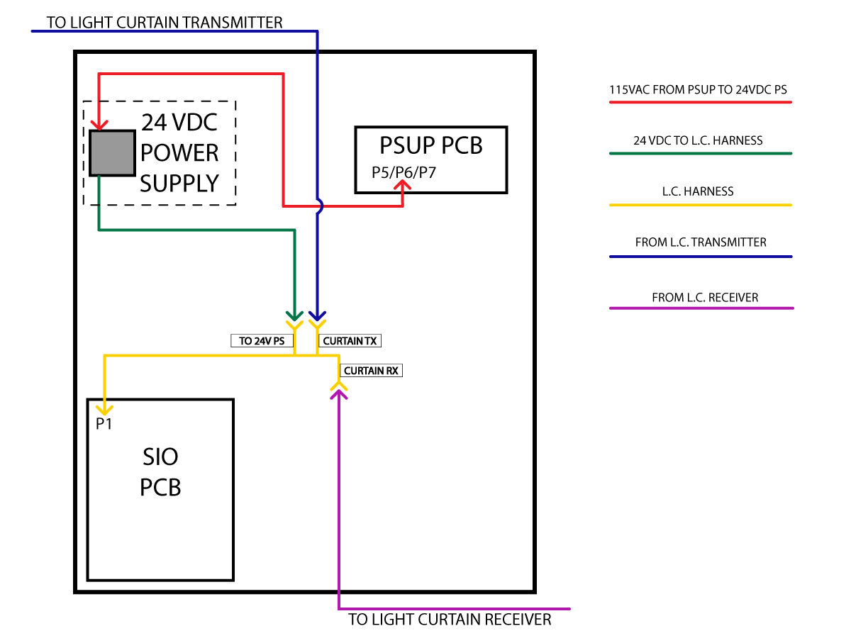
Use the provided velcro patch to attach the 24VDC power supply to the right wall inside the control cabinet.

Interconnect the light curtain cables as shown on the diagram.

If plugs P5/6/7 are not available on the PSUP PCB. Remove a fan power cable from P5/6/7 and plug in 33-7180 CBL FAN ADAPTER TO DUAL FAN. Plug in the fan power cable and light curtain power cable into 33-7180.

Fence Installation with Interlock

For a Fence Installation Instead of the light curtain follow the below procedure.

Haas Automatic Parts Loader (APL) - Fence Installation

First Power On

1

  • Note: APL's ship with the AW servo motor brake cable disconnected as a safety precaution.  This is to prevent the AW axis from dropping if the APL has not been enabled in the control.
  • Connect the AW axis servo motor brake cable
  • Power Up the machine with the E-STOP depressed
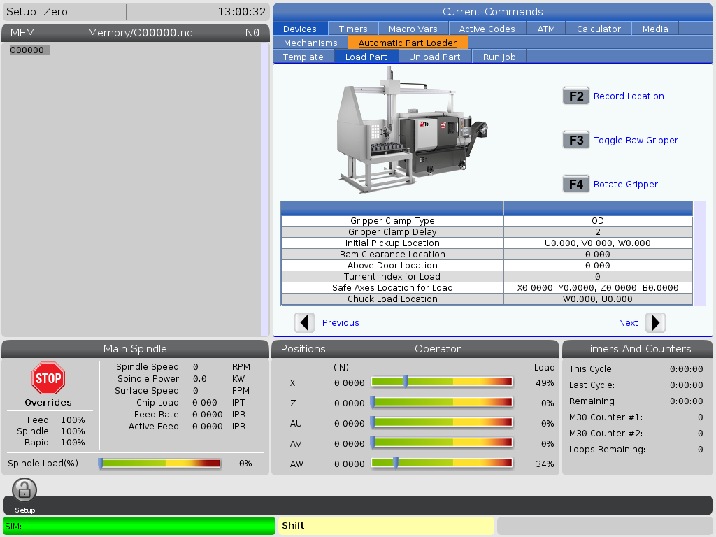
  • Before releasing the E-STOP, navigate to the CURRENT COMMANDS screen and make sure that the AUTOMATIC PART LOADER tab is visible.
  • Navigate to the ALARMS AND MESSAGES and make sure that there are no active alarms associated with the AU, AV and AW axes
  • Warning:  If the APL is left disabled and the E-STOP is released the AW axis will fall
  • Release the E-STOP and zero return the machine

Set Grid Offsets

1

  • Set Grid Offsets for AU, AV, and AW axes:
  • Zero Return AU, AV, and AW
  • Go to the Diagnostics Tab> Parameters > Factory Settings
    • Press AU + F4
    • Press AV + F4
    • Press AW + F4

Align Gripper to the Vice

1

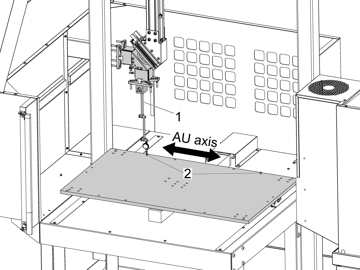
  • Mount an indicator base clamped to the gripper [1] 
  • Jog the AU axis and measure the offset between the dowel pins [2] on the APL table to verify the table is in line with AU axis motion - NTE 0.060" (1.5mm).

2

  • Jog the AU and AW axes to place the gripper [1] in front of the automatic vice [2]
  • If necessary move the APL base [3]  front to back until the stock is aligned with the vice
  • Note: Make sure the entire APL assembly stays perpendicular with machine when you move the base

Anchoring Instructions

1

  • Use a pen [1] to put a mark on the floor at the location of each foot.
  •  Note: Turn the feet to the sides of the APL to avoid a tripping hazard.
  • Drill [2]  Ø 0.50" (13 mm) hole in each mark.
  • Drill the hole to a depth of 2.0" (51 mm).

2

  • Put the foot [3] over the hole [4]
  • Put an anchor [2] into the hole
  • Use a hammer [1] to tap the anchor
  • Tap the anchor until it is at the bottom of the hole
  • Put a washer [6] and a nut [5] on the bolt
  • Torque each nut to 55 ft-lb (75 Nm)

Disable the APL

 Warning: If you turn Setting 372 to None, the AW - axis will drop if not supported or disconnected. Do one of the following:

  • Jog to a safe location
  • Unplug all APL cables BERFORE releasing E-STOP
  • Unplug AW brake BEFORE releasing E-STOP

To disable the APL to run the machine in stand-alone mode. Press [SETTING]. Change the following Settings:

  • 372 Parts Loader Type to 0: None
  • 376 Light Curtain Enabled to Off


2.2 Lathe - APL

Recently Updated

Haas Automatic Parts Loader (APL) - Lathe - Installation


AD0448

Revision A - 04/2025

Introduction

This document explains how to assemble and install the Haas Automatic Parts Loader (APL) for a Lathe.

Machine Requirements:

  • NGC/Software Version 100.19.000.1100 or greater
  • ST-10/15/20/25 Reboot Sheet Metal (Flat Face)
  • Autodoor
  • RJH-T
  • I/O PCB Hinge Door. 93-1000297 I/O DOOR ASSY HINGED
  • Check the Layout Drawing document for Machine Specifications such as Turret and Y-Axis requirements 

NOTE: Before installing the APL make sure that the lathe is leveled and the distance from the floor to the casting is 3 inches.

APL's that are purchased separate from the machine need to order the field install automation parameters kit that corresponds to how the APL will be used on the machine.

Important: This also applies when the APL is being moved from one machine to another. The machine that the APL is moving to needs to purchase the kit below in order to have the correct configuration.

After the kit is purchased, the configuration for needs to be re-uploaded to the machine from HBC.

Field Install Kit Kit Description
93-1000997 - Front Automation Safety Parameter Only Front Loading APL Safety Parameter

 Important: HE machines with an autodoor that are ordered with a robot or APL will not come with an edge sensor because these automation options come with a fence. If the machine is going to be ran without the automation option that has the fence, you will need to order and install an edge sensor for the machine. Reference the applicable edge sensor procedures for the correct part number to order:

  • Mill Edge Sensor Install
  • Lathe Edge Sensor Install

Prepare The Lathe

1

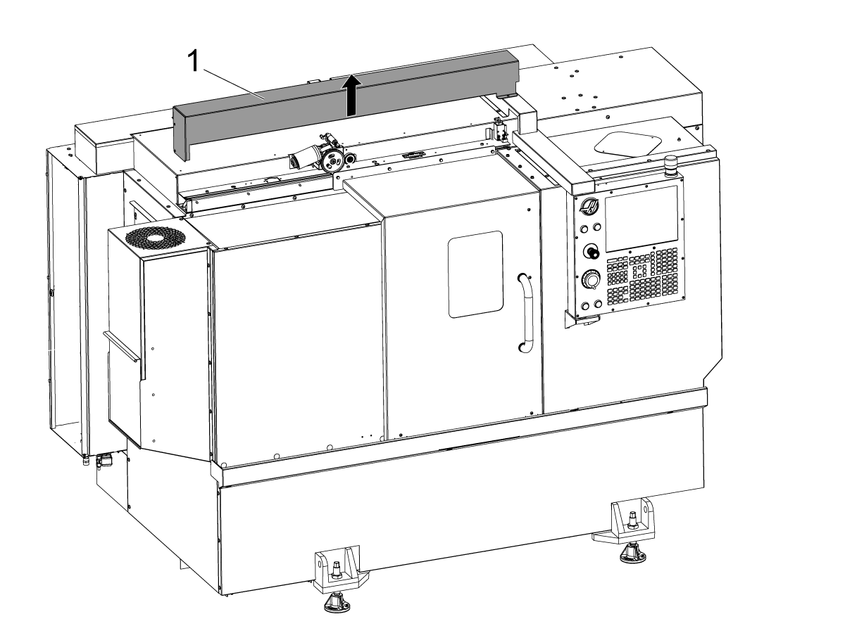
Remove the auto door cover [1].

2

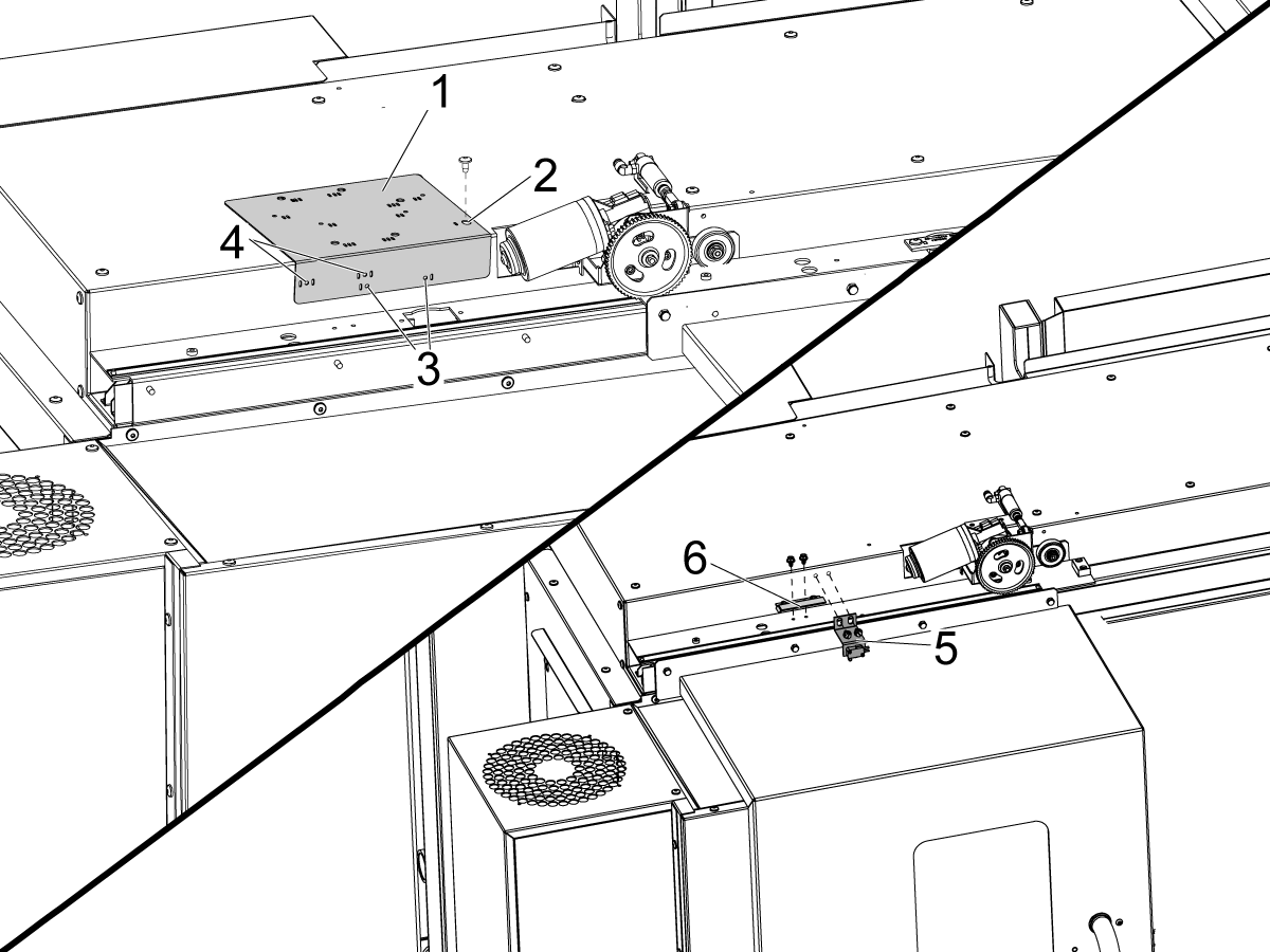
Use the provided drill guide [1] to drill the mounting holes for the DOOR FULLY OPEN status switch.

Align the right most hole on top of the drill guide that is marked with one slot [2] with the autodoor cover mounting hole to the left of the auto door motor and secure it with the BHCS.

ST-10/15:

  • Drill the two Ø 3/16" (4.7mm) mounting holes through the drill guide holes that are marked with one slots [3].

ST-20/25:

  • Drill the two Ø 3/16" (4.7mm) mounting holes through the drill guide holes that are marked with the slots on both sides [4].

Using the provided self tapping screws, install the DOOR FULLY OPEN switch assembly [5] and the DOOR FULLY OPEN trip flag [6].

3

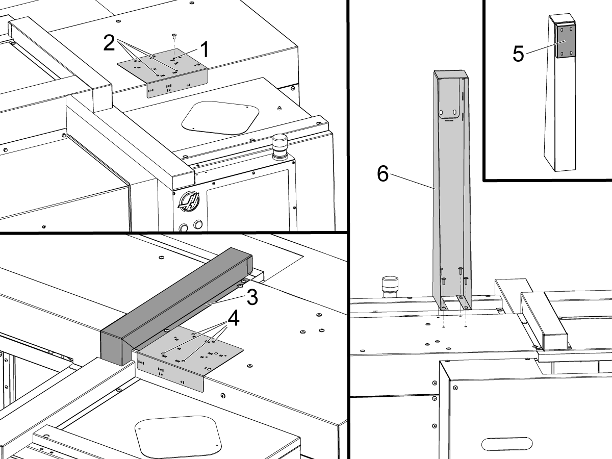
ST-10/15:

  • Align the right most drill guide hole [1] that marked with three slots next to it with the existing pemnut on top of the roof panel and secure it with the BHCS.
  • Drill the four Ø 11/32" (8.7mm) mounting holes through the drill guide holes [2] that are also marked with the three slots.

ST-20/25:

  • Place the drill guide up against the cable cover [3] flange as shown in the picture.
  • Drill the four Ø 11/32" (8.7mm) mounting holes through the drill guide holes [4] that are marked with the three slots.

Install the support pillar [6] onto the machine (with the beam mounting flange [5] facing the front of the machine) using the BHCS and the nuts on the underside of the roof panel. 


4

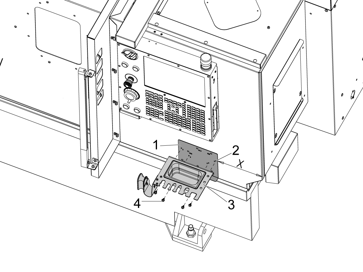
For machines with a Light Curtain and Small Tooling Tray:

Remove the tooling tray bracket that is attached to the bottom of the pendant.

ST-10/15:

  • Place the drill guide [1] against the front panel, 8 inches (203mm) away from the right corner of the enclosure.

ST-20/25:

  • Place the drill guide [1] against the front panel, 17.75 inches (450mm) away from the right corner of the enclosure.

Drill the four Ø 3/16" (4.7mm) mounting holes through the drill guide holes [2] that are marked with two slots.

Remove the drill guide and attach the tooling tray [3] to the front panel using four self tapping screws [4].

5

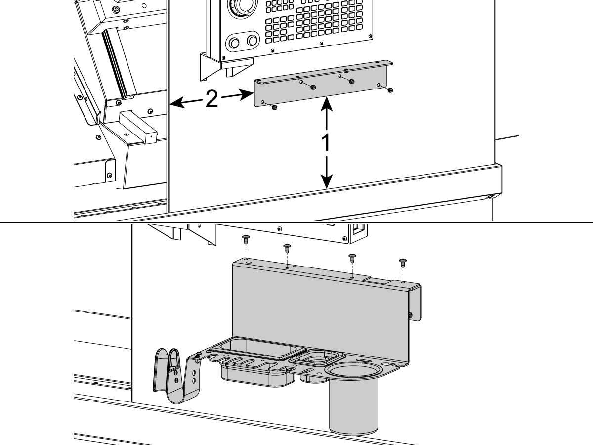
For machines with a Light Curtain and Large Tooling Tray and Tooling Tray Bracket Adapter.

Remove the tooling tray bracket that is attached to the bottom of the pendant.

Place the Tooling Tray Bracket Adapter 10.25"[1] above the door rail cover and 10.5"[2] from the door opening.

Drill the four Ø3/16" (4.7mm) mounting holes through the Bracket Adapter holes and attach the Tooling Tray Bracket Adapter to the front panel using four self tapping screws.

Mount the Tooling Tray to the Tooling Tray Bracket Adapter with button head cap screws.

6

Turn the air supply OFF

Inside the CALM cabinet, remove the NPT plug [1] from one of the CALM manifold ports

Install the push to connect fitting [2]

This is where the air line from the APL solenoid rack will be routed to the CALM cabinet

Assemble the APL & Remove Shipping Brackets

1

  • Remove table shipping brackets [1]
  • Remove AW axis shipping bracket [2]

2

To set the AU axis square to the AW axis. The bridge may be shimmed with washers[1]. These will be placed between the bridge and the shipping pad when at its shipping position.

When installing an APL look carefully for these washers [1] as you unbolt and raise the bridge. If you find washers [1] then move them to the upper pad on the same column when reinstalling the bridge.

3

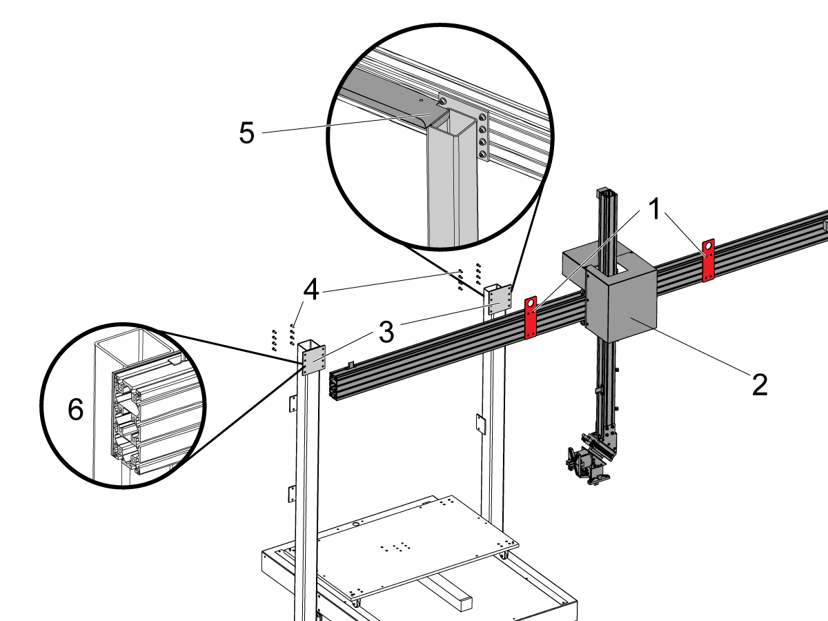
  • Move the beam from its shipping position to the top of the columns [3] using the lift fixture [1]
  • Leave the lifting brackets on so you can level the beam later after you power the APL and level the table

4

Remove the AU axis shipping brackets [1]  that are located on the back of the AW axis carriage.

Remove the AU axis servo motor cover to gain access to the W axis shipping brackets [3].

Remove the AW axis shipping brackets [3].

Reinstall the AU axis servo motor cover [2].

5

Air supply should be connected, if it is turn it off.

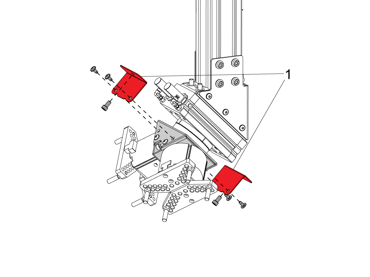
Remove the shipping brackets [1] from the rotator.

Reinstall the bolts.

 NOTE: The gripper assembly will rotate in position as soon as the air supply is turned back ON.

6

Route the AU and AW axes cables with the air lines down through the pillar [1].

Connect the air lines to the solenoids in accordance with the decal.

Install the provided conduit tube over the air lines to protect it from damage.

Connect each solenoid cable to the corresponding connection on the manifold bracket under the solenoids.

7

The cable carrier bracket [1] and its hardware can be found in a bag zip tied to the APL.

Install the cable carrier bracket [1] as shown with the provided hardware.

Verify that the bracket [2] is sitting on top of the APL edge [3] as shown, this will help ensure the cable carrier does not get caught on the edge.

8

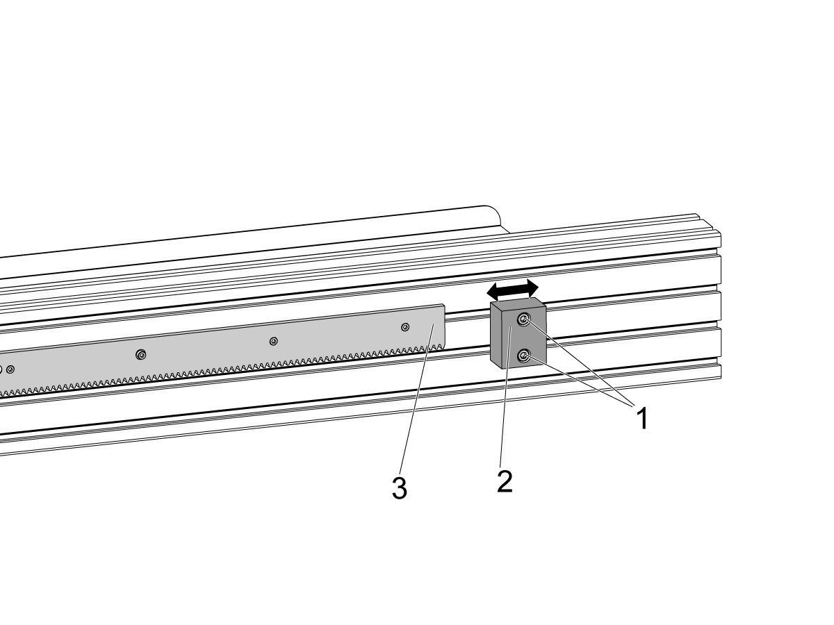
Brake loose the bolts [1] that secure the right side hard stop block [2].

Position the hard stop block [2] 0.75 inches (19mm) away from the edge of the rack gear assembly [3].

Torque the hard stop mounting bolts to 25 ft-lbs (33.9 Nm).

9

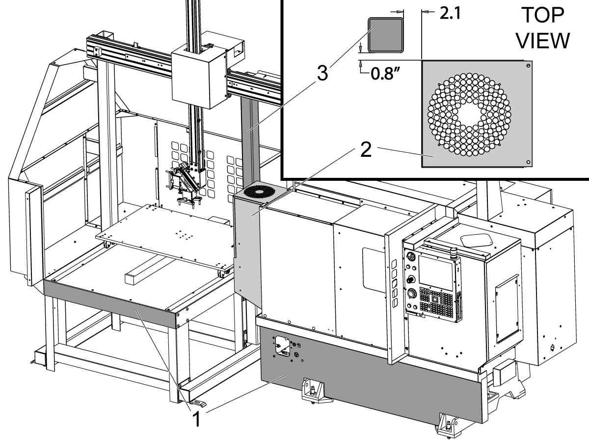
Make sure that the front edge of the APL and the front of the machine are parallel. [1]

Use the provided measurements between spindle motor cover [2] and the right APL pillar [3] to place the APL on the left side of the machine.

NOTE: Dimensions are in inches.

Enable the APL

1

Important:  Perform this step before installing electrical APL components to the machine. 

Warning:  If the machine does not have the APL enabled it could drop the AW axis if the AW axis is connected.

The AW axis servo brake cable is disconnected to prevent the AW axis from falling if the APL is not enabled and the machine is powered on.  

  • E-STOP the machine.
  • Change parameter 2191 LIGHT CURTAIN TYPE to LC_TYPE_1
  • Change parameter 2194 ENABLE FRONT DOOR FULLY OPEN SWITCH to TRUE
  • Set the setting 372 PARTS LOADER TYPE to Lathe APL
  • Set the setting 375 APL GRIPPER TYPE to Right Angle Rotator Dual Gripper
  • Set the Setting 376 LIGHT CURTAIN ENABLE to ON
  • Keep the E-STOP depressed and power the machine OFF

Note: The control needs to be in service mode to access the Factory Settings menu.

Follow the electrical installation to connect the APL to the machine

Be sure to connect the AW servo motor brake cable

Electrical Installation

1

Install the AU, AV and AW axes amplifiers in the respect with the decal labels on the amplifier fan bracket .

NOTE: AU axis amplifier [1] shown on the picture.

2

NOTE: Skip this step if the machine has Live Tooling, Y axis or the Sub-Spindle option. Machines that were built with the  Live Tooling, Y axis and the Sub-Spindle  will have an additional ammplifier bank to the left of the Vector Drive and  will come with the dual lead DC BUS cable installed from the factory.

If the machine was built with the single lead DC buss cable (33-04901B) you will need to replace it with the dual lead DC BUS cable (33-0052C) provided with the kit.

Before working on this cable, power the machine OFF and allow the Vector Drive capacitors to discharge until the red light [1] on the Vector Drive is OFF.

Remove the old cable that supplies DC voltage from the Vector Drive terminals 2 and 3 to the amplifiers.

Install the new dual lead DC BUS cable (33-0052C) as follows:

  • Connect the end with the ring terminals [2] to the terminal 2 and 3 on the Vector Drive:
    • The white lead that is labeled TB2 "+" to the terminal 2
    • The black lead that is labeled TB3 "-" to the terminal 3
  • Route the longer cable through the fan bracket under the amplifiers and connect it to the "+" H.V. and the "-" H.V. terminals on the left most servo amplifier [3] as labeled.
  • Connect the remaining cable to the "+" H.V. and the "-" H.V. terminals on the right most servo amplifier [4] as labeled.

3

Route the AU, AV and AW axes power cables through the opening on the bottom of the control cabinet.

Connect the power cable leads to the high voltage terminals:

  • red to RED [1]
  • white to WHT [2]
  • black to BLK [3]

 NOTE: The AV axis power cable leads are labeled PH-A, PH-B and PH-C due to a different color scheme. Connect as follows:

  • PH-A to RED
  • PH-B to WHT
  • PH-C to BLK

Connect the ground wire [4] to the bracket for the amplifier fan.

Find the high-voltage terminals [5] on the nearest amplifier.

Find the high-voltage terminals [7] on the amplifier.

Install the jumpers [6] from the installation kit between these terminals.

Connect the black wire to -H.V. Connect the red wire to +H.V.

4

Connect the current command cables to the connector near the top of the each amplifier [1].

Connect the other ends of the cables to the AMPLIFIER COMMAND outputs on the NGC PCB [2] as follows:

  • AU axis to the output 13.
  • AV axis to the output 15.
  • AW axis to the output 16.

Route the U, V and W axes encoder cables through the opening on the bottom of the control cabinet and connect them to the ENCODER inputs on the NGC PCB [3] as follows:

  • AU axis to the input 13.
  • AV axis to the input 15.
  • AW axis to the input 16.

Route the AW axis brake cable into the control cabinet and connect it to P3/4/5 on the SIO.

5

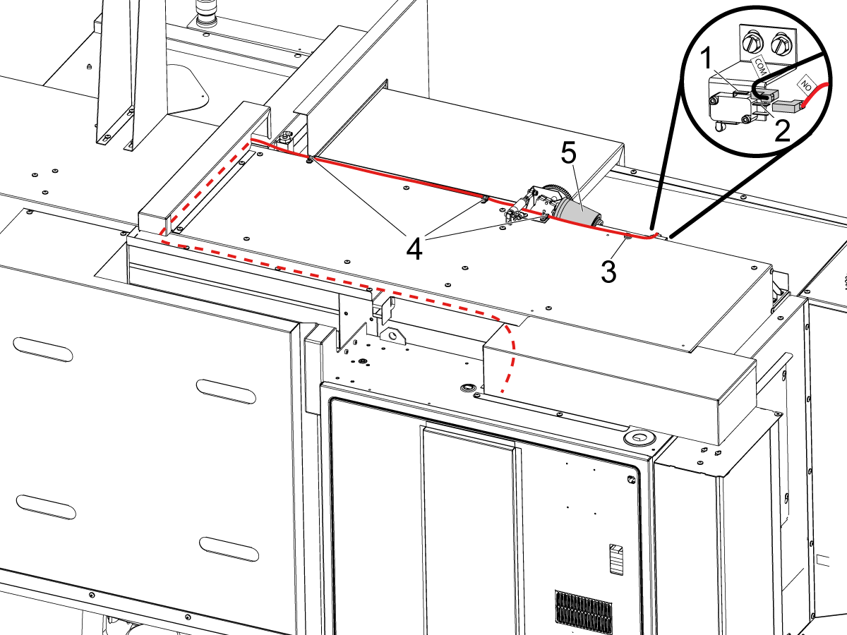
Connect the DOOR FULLY OPEN switch as labeled:

  • COM to the top terminal [1].
  • NO to the middle terminal [2].

Route the cable into the control cabinet as shown on the picture.

 NOTE: Make sure to install the provided magnetic clip [3] and cable clamps [4] to keep the cable clear of the moving autodoor motor [5].

Connect the other end of the cable to the SIO P27 RRI Door Open input. 

Install the autodoor cover.

6

Install the SMTC PCB [1] onto the SIO door using the standoffs [2] and the screws [3].

Interconnect the SMTC PCB cables as shown on the diagram.

If the machine has a Smart CAN auto door, plug cable 33-1518 into P15 on the SIO board. 

I/O PCB Hinge Door - Installation

APL E-Stop - Install

1

Attach the APL E-Stop as shown and route the cable along the bottom so that it groups up with the other cables that route to the control cabinet.

2

Connect the APL E-Stop button wire to TB1 on the I/O Board.

Remove jumper from JP1 on the I/O PCB.

Change factory setting: 1278 [1278]: Robot Ready E-Stop Enabled to True

Level the APL

1

Level the APL base with the bubble level on top of the APL table.

Use the leveling screws at the bottom of the APL base to level the APL front to back [1] and side to side [2].

When done with leveling make sure that all four leveling screws make contact with the floor.

2

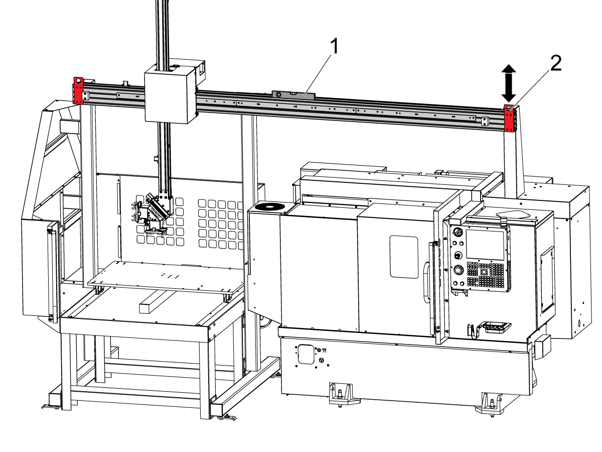
Place the bubble level [1] on top of the horizontal beam.

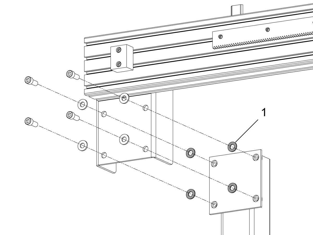
Loosen the bolts that secure the beam to the pillars.

Lift or lower the right side [2] of the horizontal beam until it leveled.

Tighten the bolts that secure the horizontal beam to the pillars.

Remove the lifting brackets. 

Light Curtain Installation

1

 NOTE: For Machines with light curtain perform this section. 

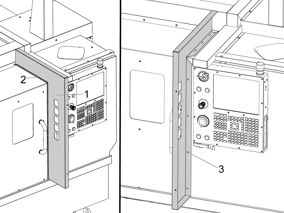
Place the light curtain mount [1] flush with the right door opening edge [2].

Mark and drill seven Ø 3/16" (4.7mm) mounting holes [3].

Attach the light curtain mount to the machine using the self tapping screws. 

NOTE: You can route the light curtain cable at this point to avoid reinstalling the self tapping screws. 

2

Assemble the light curtain mounting brackets as shown on the picture [1].

 NOTE: The light curtain kit contains the transmitter and the receiver. You can identify these by the sticker on the side of the housing. It is labeled "RECEIVER" [2] and "TRANSMITTER" [3]. 

When installing the light curtains make sure that the end with the cable connection is on the bottom.

Install the light curtain receiver [4] on the lathe side.

Install the light curtain transmitter [5] on the APL side.

Make sure that the transmitter and the receiver are pointed at each other before tightening the mounting bolts.

Route the Transmitter cable [6] and the Receiver [7] cable into the control cabinet as shown.


3

Use the provided velcro patch to attach the 24VDC power supply to the right wall inside the control cabinet.

Interconnect the light curtain cables as shown on the diagram.

If plugs P5/6/7 are not available on the PSUP PCB. Remove a fan power cable from P5/6/7 and plug in 33-7180 CBL FAN ADAPTER TO DUAL FAN. Plug in the fan power cable and light curtain power cable into 33-7180.

Fence Installation with Interlock

For a Fence Installation Instead of the light curtain follow the below procedure.

Haas Automatic Parts Loader (APL) - Fence Installation

First Power-UP

1

 Caution: The AW-Axis brake cable is disconnected during shipping as a safety precaution.  If the APL is not enabled in the control, the AW axis can drop on the table if powered on.  Make sure the APL is enabled before plugging in the brake cable.

Connect the AW Axis brake cable.

Power Up the machine with the E-STOP depressed.

Before releasing the E-STOP, navigate to the CURRENT COMMANDS screen and make sure that the AUTOMATIC PART LOADER tab is visible. 

Navigate to the ALARMS AND MESSAGES and make sure that there is no active alarms associated with the AU, AV and AW axes.

 NOTE:  If the APL is left disabled, and the E-STOP is released, the AW axis will fall.

Release the E-STOP and zero return the machine.

Set the GRID offsets for the AU, AV and the AW axes. Refer to the Axis Grid Offset - NGC.

Set Offsets

1

  • Set Grid Offsets for AU, AV, and AW axes:
  • Zero Return AU, AV, and AW
  • Go to the Diagnostics Tab> Parameters > Factory Settings
    • Press AU + F4
    • Press AV + F4
    • Press AW + F4

2

  • Set Tool Change Offset
  • Put small puck template on table.
  • Place 2” diameter puck in front left position on template
  • Align Gripper 1 in AU and AV to the puck
  • Set Tool Change Offset
  • Diagnostics -> Parameter -> Factory
    • AU + F2
    • AV + F2

Align the Gripper to the Spindle

1

With an indicator base clamped to the gripper [1] Jog the AU axis and measure if the dowel pins [2] on the APL table is inline with the AU axis motion. NTE 0.060" (1.5mm).

If your machine does not have the new linear rail kit please complete the retrofit procedure per APL Linear Rail Retrofit Kit Installation

2

Clamp the piece of round stock [1] in the APL gripper 1.

Note: Using machined jaws will increase accuracy

Jog AU and AW axes to place the gripper with the round stock in front of the spindle chuck [2].

Move the APL base [3] front to back with a pallet jack until the piece of round stock [1] align with the spindle.

 NOTE: When moving the APL base, make sure that the APL beam support [4] pillar moves the same amount and the front of the APL stays parallel to the front of the machine.

Jog the AU axis and place the stock into the chuck.

Open and close the chuck and check for deflection of the AW arm

Move the table back forth, and the AW axis up and down until there is minimal movement when the chuck clamps on the stock.

Check Gripper number 2 in the same way.

Once the APL grippers aligned with the spindle, tighten the bolts that secure the APL beam support to the roof panel [4].

3

Fine front-to-back adjustment of the gripper.

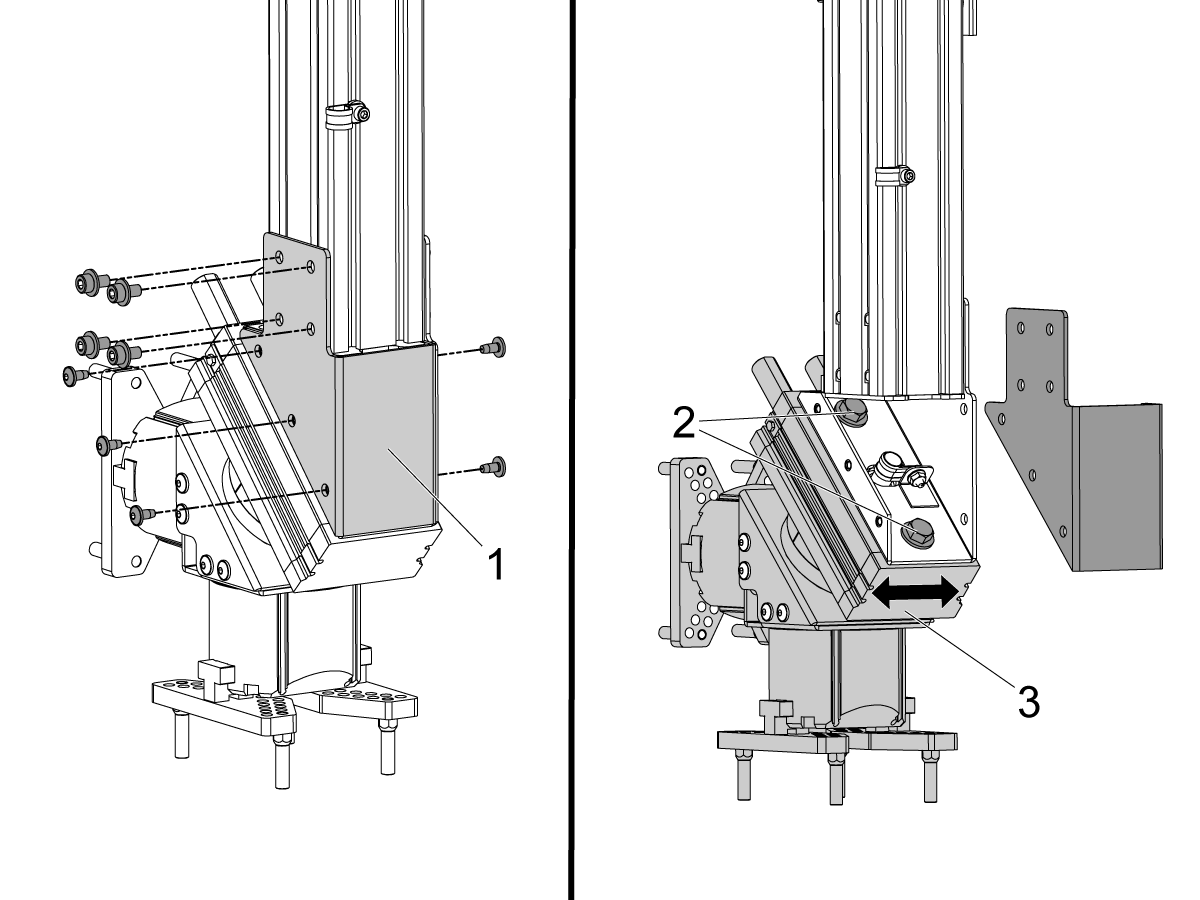
Remove the bolts that keep the rotator extrusion cover [1] in place.

Remove the rotator extrusion cover.

Break loose two bolts [2] that secure the rotator [3] to the bracket. This will allow you to move the gripper assembly front to back.

Once the gripper assembly is in desired position, torque the two mounting bolts [2] to 60 ft-lbs (81 Nm) and install the rotator extrusion cover.

Torque the four SHCS [4] to 20 ft-lbs (27 Nm) 


4

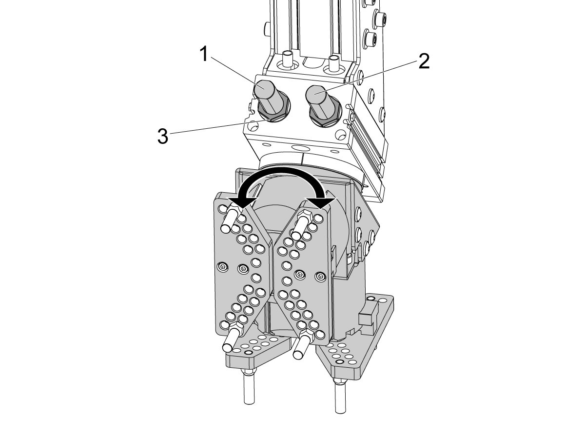
Set rotator limits. 

The rotator clockwise (CW) and counterclockwise (CCW) limits are set with the stop screws on top of the rotator unit. There is a stop screw for the CW limit [1] and the CCW limit [2]. 

To adjust the CW limit:

  • Break loose the jam nut [3].
  • Rotate the gripper assembly clockwise until it stops against the stop screw.
  • Turn the CW stop screw in or out to manipulate the CW limit position.
  • Once the rotator is in desired CW limit position, hold the CW stop screw with the wrench and tighten the jam nut [3].

Use the CCW stop screw [2] to set the CCW limit.

Use a magnetic base and indicator on the table to indicate the side of the gripper plate while moving the AW axis up and down.  Adjust rotator limits until this is relatively parallel with the AW axis.

Install APL Spring Pusher to Turret

1

  • The APL spring pusher is made with a shank to fit either a 25mm or 1” tool holder
  • This tool must take up a toolholder on the turret
  • If the machine is a ST-10/15 you will need two empty toolholders to allow enough space for the gripper
  • Program the following steps to the beginning of any Lathe APL program to make sure the part is properly seated into the chuck:
    • Locate the spring pusher in front of the part
    • Move the Z axis to compress the spring about 0.50 inches or 12.7 mm
    • Open the chuck with a dwell of one second
    • Close the chuck with a dwell of one second
    • Retract the turret to the safest position possible

Anchoring Instructions

1

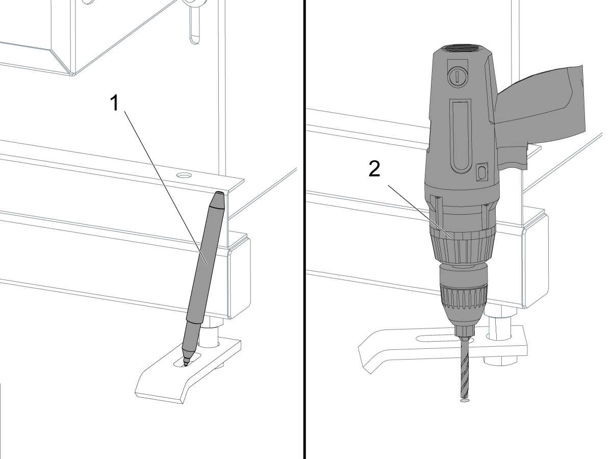
  • Use a pen [1] to put a mark on the floor at the location of each foot.
  •  Note: Turn the feet to the sides of the APL to avoid a tripping hazard.
  • Drill [2]  Ø 0.50" (13 mm) hole in each mark.
  • Drill the hole to a depth of 2.0" (51 mm).

2

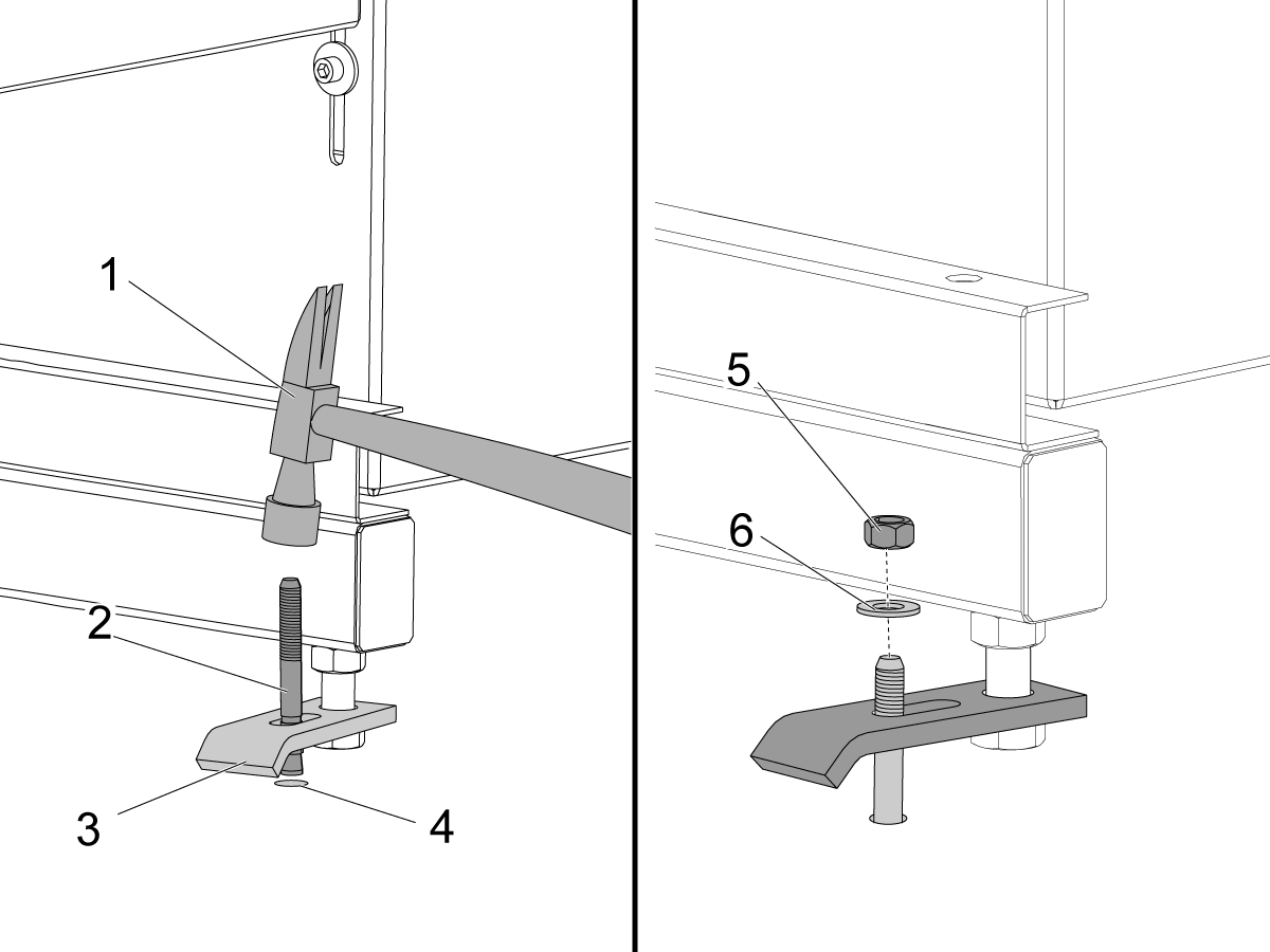
  • Put the foot [3] over the hole [4].
  • Put an anchor [2] into the hole.
  • Use a hammer [1] to tap the anchor.
  • Tap the anchor until it is at the bottom of the hole.
  • Put a washer [6] and a nut [5] on the bolt.
  • Torque each nut to 55 ft-lb (75 Nm).

Disable the APL

 Warning: If you turn Setting 372 to None, the AW - axis will drop if not supported or disconnected. Do one of the following:

  • Jog to a safe location
  • Unplug all APL cables BERFORE releasing E-STOP
  • Unplug AW brake BEFORE releasing E-STOP

To disable the APL to run the machine in stand-alone mode. Press [SETTING]. Change the following Settings:

  • 372 Parts Loader Type to 0: None
  • 376 Light Curtain Enabled to Off


2.3 UMC - APL

Recently Updated

Haas Automatic Parts Loader (APL) – UMC – Installation


AD0509

Revision A - 04/2025

Automatic Parts Loader Installation Video

The following service video shows how to install the APL on the UMC-500/SS.

Note: This service video is for reference only and does not replace the written procedure.

Introduction

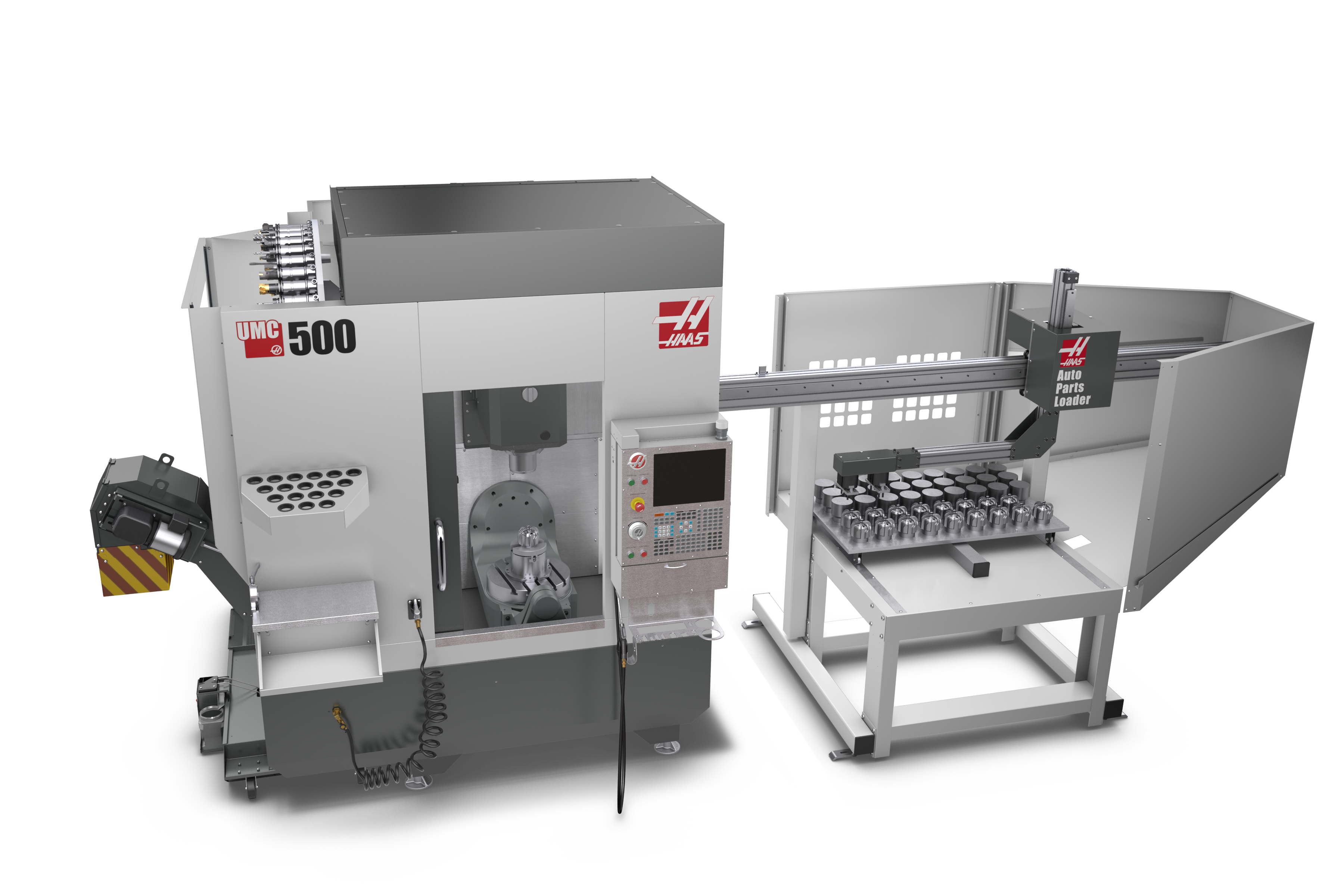
This document explains how to assemble and install the Haas Automatic Parts Loader (APL) for a UMC machine

Machine Requirements:

  • NGC/Software Version 100.23.000.1020 or higher
  • RJH-T
  • I/O PCB Hinge Door. 93-1000297 I/O DOOR ASSY HINGED
  • Check the Layout Drawing document for Machine Specifications

Note: Before installing the APL make sure that the mill is leveled and the distance from the floor to the casting is 4 inches.

 Important: HE machines with an autodoor that are ordered with a robot or APL will not come with an edge sensor because these automation options come with a fence. If the machine is going to be ran without the automation option that has the fence, you will need to order and install an edge sensor for the machine. Reference the applicable edge sensor procedures for the correct part number to order:

  • Mill Edge Sensor Install

This document can also be used to field install the APL on a UMC-400 or UMC-500

UMC Field Install Machine Requirements:

  • Field Install Kit - 93-1001187: INSTALL KIT APL SIDE UMC-400/500 NOT CE
  • NGC/Software Version 100.23.000.1020 or higher 
  • RJH-XL
  • UMC-400 built after 1/17/2025 or UMC-500 built after 3/13/2023
  • Auto Window 
    • 93-1001178: AUTO WINDOW DUAL SWITCH KIT UMC-400/SS
    • 93-1000940: AUTO WINDOW DUAL SWITCH KIT UMC-500/SS
  • 90 Degree Cabinet - Refer to the Auto Window procedure for instructions on how to rotate the electrical cabinet.
  • I/O PCB Hinge Door. 93-1000297 I/O DOOR ASSY HINGED

 Note: Before installing the APL make sure that the mill is leveled and the distance from the floor to the casting is 4 inches.

UMC-500 Field Install Safety Requirements:

The UMC-500 APL field install will need to install a light curtain or fence for safety requirements, the field install kit part numbers are below:

  • Fence Kit - 93-1001007: APL FENCE KIT UMC-500/SS CE
  • Light Curtain Kit - 93-1001008: APL LIGHT CURTAIN KIT UMC-500/SS NOT CE

APL's that are purchased separate from the machine need to order the field install automation parameters kit that corresponds to how the APL will be used on the machine.

Important: This also applies when the APL is being moved from one machine to another. The machine that the APL is moving to needs to purchase the kit below in order to have the correct configuration.

After the kit is purchased, the configuration file needs to be re-uploaded to the machine from HBC.

Field Install Kit Kit Description
93-1000996 - Side Automation Safety Parameter Only
Side Loading APL Safety Parameter

Install the HPU and Vise

1

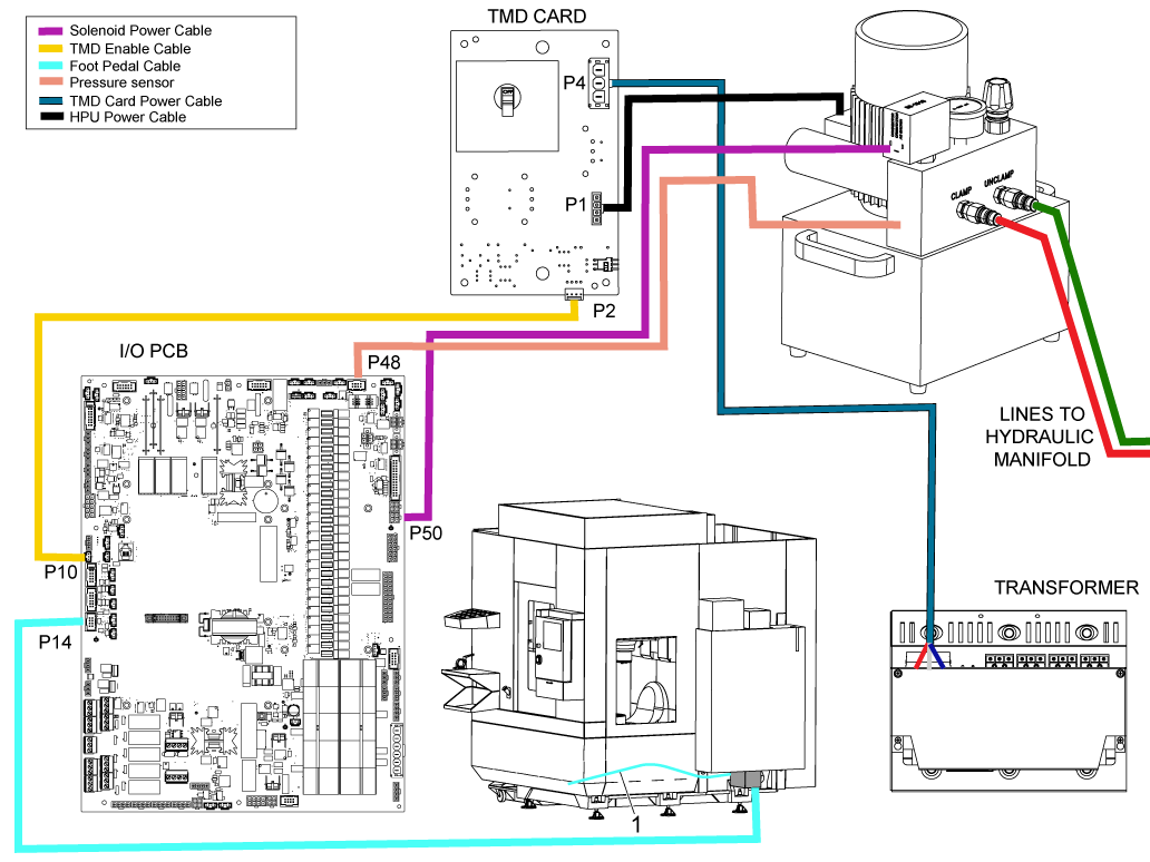
Follow the wiring diagram  for the electrical components all of the wiring will make its way through the box under the control cabinet and to the I/O board.

If the machine does not come with a I/O HINDGED DOOR you will need to install it, follow the I/O HINGED DOOR PROCEDURE for instructions on how to install it.

A food pedal cable will also be routed from the front skirt [1] of the machine along the side skirt into the box under the control cabinet and connected to the I/O board as shown.

2

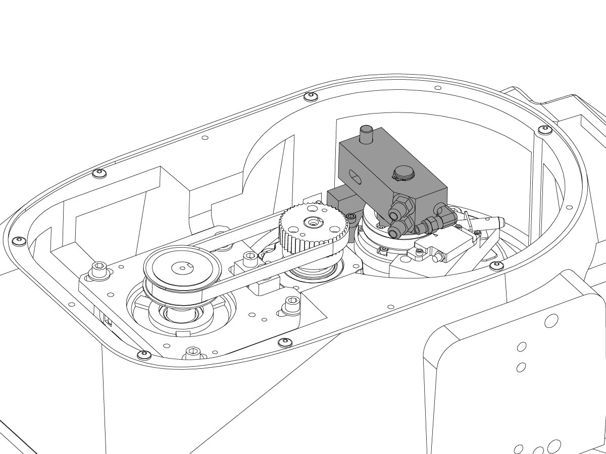
Please refer to the link to install the correct Workholding option.

UMC Hydraulic Workholding - Installation - AD0499
UMC Pneumatic Workholding - Installation - AD0542

3

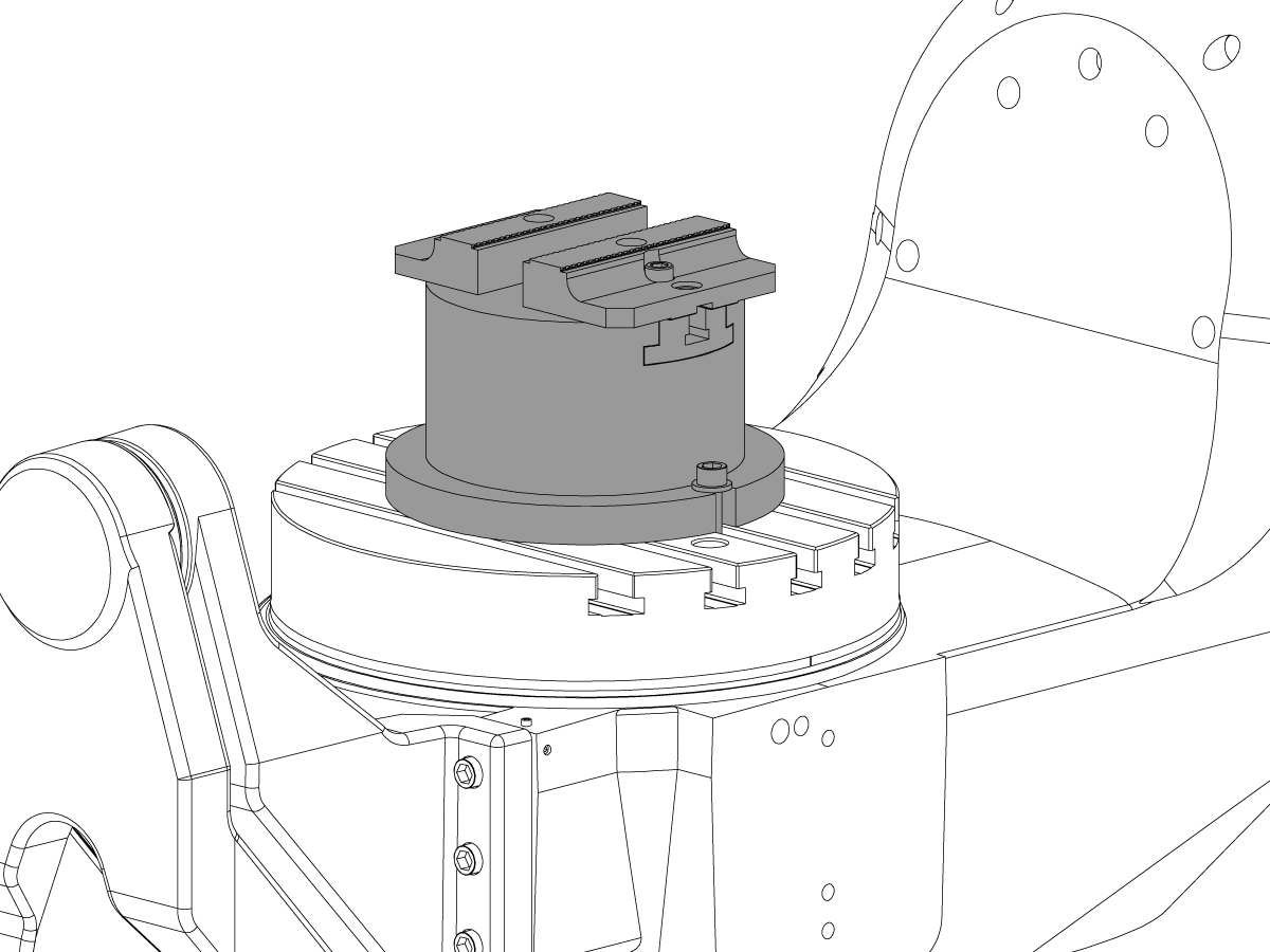
Please refer to the link to install the correct Vise option.

UMC Hydraulic Vise - Installation/Removal - AD0514
UMC Pneumatic Vise - Installation - AD0543

APL Alignment on Machines With 90 Degree Control Cabinet

1

NOTE: Perform this Section only on UMC's with the swivel Control Cabinet.  

NOTE: Machines built after April 1, 2021 are built with the swivel electrical control cabinet (also known as the 90 degree electrical control cabinet).
 
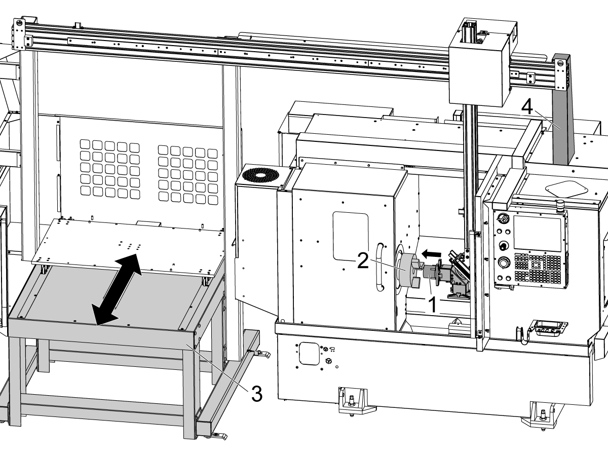
  • Use a pallet jack to move the APL [1] into the proper position.
  • adjust APL to the measurements shown:
    • Measure distance of 0.5" (13mm) for the AU Axis of APL 
    • Measure distance of 1.25" (32mm)  for the AV Axis of APL

2

Refer to this step for CE machines built after January 2024 and US APL's built after April 2024
  • Use a pallet jack to move the APL [1] into the proper position.
Placement Measurement UMC-400 UMC-500
Autowindow cover to AV axis front face [1] 3.33 inches (85mm) 1.5 inches   (38mm)
Autowindow cover to AU axis face [2] 0.25 inches (6.35mm) 0.5 inches (13mm)

3

Refer to this step for CE/Fence APL's built January 2024 and later
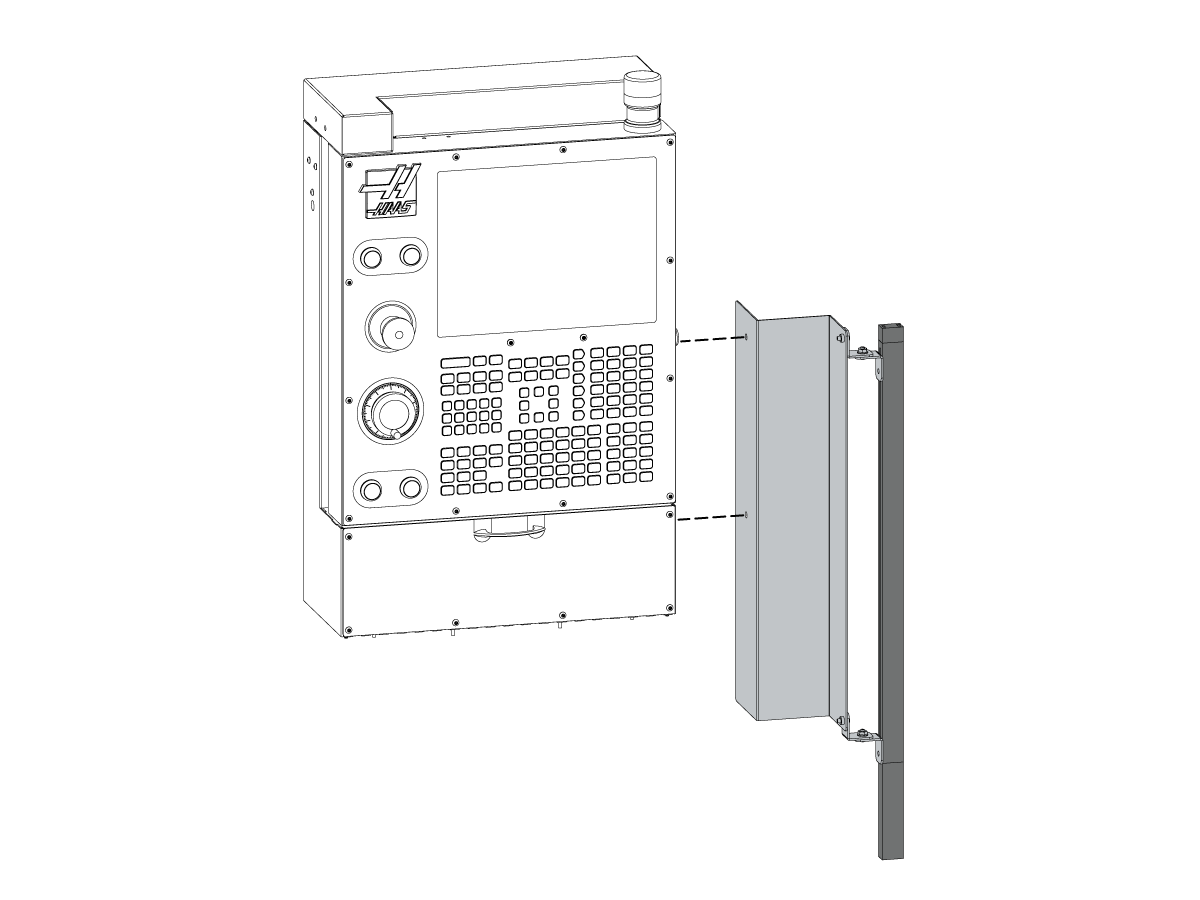
  • Install the APL enclosure panel [1] to the UMC Cntrol Cabinet as shown.

4

Refer to this step for US APL's built before April 2024
  • Install the APL enclosure panel [1] to the electrical control cabinet.

5

Refer to this step for Non CE/Fence APL's built after April 2024
  • Install the APL enclosure panel [1] to the UMC's enclosure using the magnets provided as shown.

Level the APL

1

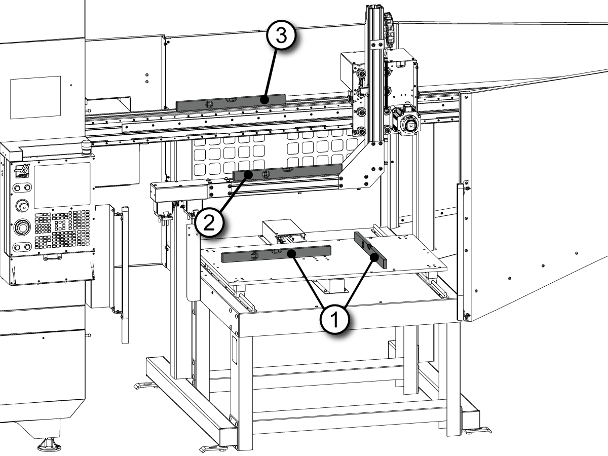
  • Level the APL base with the bubble level on top of the APL table
  • Use the leveling screws at the bottom of the APL base to level the APL front to back and side to side [1]
  • When done with leveling make sure that all four leveling scerws make contact with the floor
  • Place the level on top of the horizontal beam [3]
  • Loosen the bolts that secure the beam to the pillars
  • Lift or lower the right side of the horizontal beam until it is leveled
  • Tighten the bolts that secure the horizontal beam to the pillars
  • Verify APL Arm Level [2]

Shipping Brackets

1

  • Remove the APL arm shipping bracket [1]

2

  • Remove the table shipping brackets [1], [2]

3

  • Remove the AW axes sheet metal shroud [2]
  • Remove the AU and AW axes shipping brackets [1]

UMC Preperation

1

  • Route the conduit from the apl to the UMC electrical control cabinet as shown.
Illustration [1] shows a UMC with a fixed electrical control cabinet.
Illustration [2] shows a UMC with a swivel electrical control cabinet. 

NOTE: Machines built after April 1, 2021 are built with the swivel electrical control cabinet (also known as the 90 degree electrical control cabinet).
 
  • Inside this conduit are several wires and a pneumatic line from the APL manifold used to aupply air to the gripper solenoids
  • Feed all wires from conduit into the control cabinet except for the pneumatic line.

2

  • One end of the pneumatic line is connected to the APL manifold [1]
  • The other end is routed through the manifold shown in the previous step but, instead of being fed into the electrical cabinet, is routed to the CALM cabinet [2]

3

  • Verify the push-connect fitting on the side of the APL manifold is connected securely. 

4

  • Connect the other end of the hose to the CALM manifold at the location shown using the appropriate adaptor fitting to do so.

Light Curtain - Installation

1

 NOTE: For Machines with light curtain perform this section.   
  • Bolt the transmitter end of the light curtain to the side of the APL enclosure using the provided hardware in the configuration shown.
  • When installing the light curtains make sure that the end with the cable connection is on the bottom
  • Run cable from bottom of transmitter under the pallet pool and through the wire conduit

2

  • Bolt the reciever end of the light curtain to the left side of the controller using the provided hardware in the configuration shown.
  • When installing the light curtains make sure that the end with the cable connection is on the bottom

3

  • Use the provided velcro patch to attach the 24VDC power supply to the right wall inside the control cabinet
  • Interconnect the light curtain cables as shown on the diagram

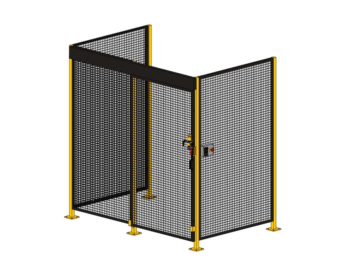
Fence Installation with Interlock

For a Fence Installation Instead of the light curtain follow the below procedure.

Haas Automatic Parts Loader (APL) - Fence Installation

Enable the APL

1

 WARNING: Perform this step before connecting electrical APL components to the machine.

Note: The control needs to be in Service Mode to access the Factory Settings menu

  • E-STOP the machine
  • Change parameter 2191 LIGHT CURTAIN TYPE to LC_TYPE_1
  • Set the setting 372 PARTS LOADER TYPE to TYPE 2 MILL APL
  • Set the setting 375 APL GRIPPER TYPE to Dual Gripper
  • Set the Setting 376 LIGHT CURTAIN ENABLE to ON
  • Keep the E-STOP depressed and power the machine OFF


Electrical Installation

1

  • Install the AU, AV and AW axes amplifiers in the respect with the decal labels on the amplifier fan bracket 

Note: AU axis amplifier [1] shown on the picture

2

  • If the machine was built with the single lead DC buss cable (33-04901B) you will need to replace it with the dual lead DC BUS cable (33-0052C) provided with the kit
  • Before working on this cable, power the machine OFF and allow the Vector Drive capacitors to discharge until the red light [1] on the Vector Drive is OFF
  • Remove the old cable that supplies DC voltage from the Vector Drive terminals 2 and 3 to the alplifiers
  • Install the new dual lead DC BUS cable (33-0052C) as follows:
    • Connect the end with the ring terminals [2] to the terminal 2 and 3 on the Vector Drive:
      • The white lead that is labeled TB2 "+" to the terminal 2
      • The black lead that is labeled TB3 "-" to the terminal 3
  • Route the longer cable through the fan bracket under the amplifiers and connect it to the "+" H.V. and the "-" H.V. terminals on the left most servo amplifier [3] as labeled
  • Connect the remaining cable to the "+" H.V. and the "-" H.V. terminals on the right most servo amplifier [4] as labeled


3

  • Route the AU, AV and AW axes power cables through the opening on the bottom of the control cabinet
  • Connect the power cable leads to the high voltage terminals Note: The AV axis power cable leads are labeled PH-A, PH-B and PH-C due to a different color scheme. Connect as follows::
    • red to RED [1]
    • white to WHT [2]
    • black to BLK [3]
    • PH-A to RED
    • PH-B to WHT
    • PH-C to BLK
  • Connect the ground wire [4] to the bracket for the amplifier fan
  • Find the high-voltage terminals [5] on the nearest amplifier
  • Find the high-voltage terminals [7] on the amplifier
  • Install the jumpers [6] from the installation kit between these terminals
  • Connect the black wire to -H.V. Connect the red wire to +H.V.

4

  • Connect the current command cables to the connector near the top of the each amplifier [1]
  • Connect the other ends of the cables to the AMPLIFIER COMMAND outputs on the NGC PCB [2] as follows:
    • AU axis to the output 8
    • AV axis to the output 15
    • AW axis to the output 16
  • Route the U, V and W axes encoder cables through the opening on the bottom of the control cabinet and connect them to the ENCODER inputs on the NGC PCB [3] as follows:
    • AU axis to the input 8
    • AV axis to the input 15
    • AW axis to the input 16
  • Route the AW axis brake cable into the control cabinet and connect it to P3/4/5 on the SIO

5

Install the SMTC PCB [1] onto the SIO door using the standoffs [2] and the screws [3].

Interconnect the SMTC PCB cables as shown on the diagram.

If the machine has a Smart CAN auto door, plug cable 33-1518 into P15 on the SIO board. 

First Power On

1

  •  Note: APL's ship with the AW servo motor brake cable disconnected as a safety precaution.  This is to prevent the AW axis from dropping if the APL has not been enabled in the control.
  • Connect the AW axis servo motor brake cable
  • Power Up the machine with the E-STOP depressed
  • Before releasing the E-STOP, navigate to the CURRENT COMMANDS screen and make sure that the AUTOMATIC PART LOADER tab is visible.
  • Navigate to the ALARMS AND MESSAGES and make sure that there are no active alarms associated with the AU, AV and AW axes
  •  Warning:  If the APL is left disabled and the E-STOP is released the AW axis will fall
  • Release the E-STOP and zero return the machine

Set Offsets

1

  • Set Grid Offsets for AU, AV, and AW axes:
  • Zero Return AU, AV, and AW
  • Go to the Diagnostics Tab> Parameters > Factory Settings
    • Press AU + F4
    • Press AV + F4
    • Press AW + F4

2

  • Jog the C axis until vise is set to the position as shown
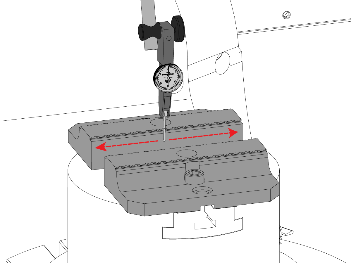
  • Run indicator along entire length of 6" jaw until runnout is within tolerance (NTE +/- 0.001)
  • Save this position under Factory Parameter 7.310 as your new C-Axis Pallet Offset. The C-Axis will rotate to this position for every part change.

Anchoring Instructions

1

  • Use a pen [1] to put a mark on the floor at the location of each foot.
  •  Note: Turn the feet to the sides of the APL to avoid a tripping hazard.
  • Drill [2]  Ø 0.50" (13 mm) hole in each mark.
  • Drill the hole to a depth of 2.0" (51 mm).

2

  • Put the foot [3] over the hole [4]
  • Put an anchor [2] into the hole
  • Use a hammer [1] to tap the anchor
  • Tap the anchor until it is at the bottom of the hole
  • Put a washer [6] and a nut [5] on the bolt
  • Torque each nut to 55 ft-lb (75 Nm)

Disable the APL

 Warning: If you turn Setting 372 to None, the AW - axis will drop if not supported or disconnected. Do one of the following:

  • Jog to a safe location
  • Unplug all APL cables BERFORE releasing E-STOP
  • Unplug AW brake BEFORE releasing E-STOP

To disable the APL to run the machine in stand-alone mode. Press [SETTING]. Change the following Settings:

  • 372 Parts Loader Type to 0: None
  • 376 Light Curtain Enabled to Off

2.4 Compact APL

Recently Updated

Haas Compact Automatic Parts Loader (C-APL) - Installation


AD0785

Revision A - 04/2025

Introduction


This procedure outlines how to install the Compact APL on the following machines:

  • VF-2/2SS/2YT/2SSYT
  • VM-2
  • DM-1/2
  • DT-1/2
  • UMC-350HD
  • SMM/MM Reboot

Machine Requirements:

  • Software Version 100.22.000.2000 or higher
  • Machine must be ordered with the Auto Window Option.
  • REMOTE JOG HANDLE - XL 93-1000610 REMOTE JOG HANDLE TOUCH LCD (RJH-XL)
  • I/O board updated to 34-349xB or later
  • I/O PCB HINGE DOOR. 93-1000297 I/O DOOR ASSY HINGED

Note: Workholding is not included with the C-APL. It must be ordered as an additional option.

Note: Before installing the C-APL make sure that the mill is leveled and the distance from the floor to the casting is 3 inches.

 Important: HE machines with an autodoor that are ordered with a robot or APL will not come with an edge sensor because these automation options come with a fence. If the machine is going to be ran without the automation option that has the fence, you will need to order and install an edge sensor for the machine. Reference the applicable edge sensor procedures for the correct part number to order:

  • Mill Edge Sensor Install

Field Install Requirements:

  • Important: Machine must have the Auto Window installed before the C-APL. See note below.
  • Order the Compact APL
  • Field Install Kit - 93-1001107: COMPACT APL READY FIELD INSTALL KIT
  • Software Version 100.22.000.2000 or higher
  • REMOTE JOG HANDLE - XL 93-1000610 REMOTE JOG HANDLE TOUCH LCD (RJH-XL)
  • I/O board updated to 34-349xB or later
  • I/O PCB HINGE DOOR. 93-1000297 I/O DOOR ASSY HINGED

Auto Window Notes:

  • VF-2/2YT/DM/DT machines must be compatible with the Auto Window and built 4/1/2019 or later to be compatible with the Compact APL.
  • SMM/MM machines must be the new Reboot style and have the Auto Window to be compatible with the Compact APL.

Auto Window Procedures:

  • VF/VM-2 machines refer to the VMC - Auto Window - Installation procedure to order and install the correct Auto Window kit.
  • For DM/DT-1/2, UMC-350HD, and SMM/MM Reboot machines refer to the DC/DT/DM/CM/MM/SMM/UMC-350 - Auto Window - Installation procedure to order and install the correct Auto Window kit.

APL's that are purchased separate from the machine need to order the field install automation parameters kit that corresponds to how the APL will be used on the machine.

Important: This also applies when the APL is being moved from one machine to another. The machine that the APL is moving to needs to purchase the kit below in order to have the correct configuration.

After the kit is purchased, the configuration for needs to be re-uploaded to the machine from HBC.

Field Install Kit Kit Description
93-1000996 - Side Automation Safety Parameter Only
Side Loading APL Safety Parameter

Prepare the Mill

1

The cylinder for the Auto Window will need to be raised from the shipping position.

Remove the cover [1] and its hardware [2] to expose the air cylinder [4] of the automatic window on the load station and raise the air cylinder [4] so that the brackets [3] and air cylinder are attached as shown.

 Note: Do this before placing the machine and compact APL together for easier access.

Prepare the C-APL

1

Use this step for C-APL machine with the style legs shown.

The front legs should be attached to the C-APL as shown in [1].

The back legs shown be attached to the C-APL as shown in [2].

2

Use this step for C-APL machine with the style legs shown.

For DT/DM & UMC-350HD Machines:

The legs of the Compact APL should look like the top image [1]. Make sure the bolts [2] on the all legs are in the bottom four (4) holes.

For VF/VM/SMM/MM Machines:

The legs of the Compact APL should look like the top image [2]. Make sure the bolts [5] on the all legs are in the bottom four (4) holes.

3

Use this step for C-APL machine with the style legs shown.

Attach the anchoring brackets to the Compact APL as shown.

 Note: The images show how the anchoring brackets will be attached on DM/DT & UMC-350HD machines, the bolts on the brackets will need to be shifted up for Compact APL's on VF & VM machines.

4

Use this step for C-APL machine with the style legs shown.

For UMC-350HD Machines:
For a standard 100mm Haas pneumatic vise, the bolts that control the height of the legs of the Compact APL should match the layout seen in the left image [1]. The front legs should have five (5) open holes above the bolts like the top of image [1] and the back legs should have six (6) open holes above the bolts like the bottom of image [1]. Refer to the table in the Level the C-APL section below for recommended heights of the C-APL.

For DM/DT Machines:
For a standard 100mm Haas pneumatic vise, the bolts that control the height of the legs of the Compact APL should match the layout seen in the middle image [2]. The front legs should have three (3) open holes above the bolts like the top of image [2] and the back legs should have four (4) open holes above the bolts like the bottom of image [2]. Refer to the table in the Level the C-APL section below for recommended heights of the C-APL.

For VF/VM/SMM/MM Machines:
For a standard 100mm Haas pneumatic vise, the bolts that control the height of the legs of the Compact APL should match the layout seen in the right image [3]. The front legs should have one (1) open hole above the bolts like the top of image [3] and the back legs should have two (2) open holes above the bolts like the bottom of image [3]. Refer to the table in the Level the C-APL section below for recommended heights of the C-APL

5

Use this step for C-APL machine with the style legs shown.

Attach the anchoring brackets to the Compact APL as shown.

Align C-APL to the Mill

1

Use this step if the C-APL is being installed on a UMC-350/350HD

Line up the Compact APL to the machine using the locating plate as shown.  The locating plate should be placed 3 inches [1] to the left of the window as shown.

2

Use this step if the C-APL is being installed on a DT/DM-1/2

Line up the Compact APL to the machine using the locating plate as shown.  The locating plate should be placed 1/4 inch [1] to the left of the window.

3

Use this step if the C-APL is being installed on a VF/VM-2

Line up the Compact APL to the machine using the locating plate as shown.  The locating plate should be placed 5 inches [1] to the right of the window edge.

4

Use this step if the C-APL is being installed on a SMM/MM

Line up the Compact APL to the machine using the locating plate [1] as shown.  The locating plate [1] should be lined up to the left of the window [2] as shown.

5

Turn the air supply OFF

Inside the CALM cabinet, remove the NPT plug [1] from one of the CALM manifold ports and install the push to connect fitting [2].

Route the air line from the C-APL solenoid rack to the CALM cabinet and connect it to the fitting

Level the C-APL

1

Adjust the leveling feet so that the c-apl table is the same height as top of the vise jaws [1]. Use the table below for height recommendations.

Note: Make sure the C-APL is not raised too high or it may crash into the top of the auto window.

Then use a bubble level to level the Compact APL from side-to-side [2] and front-to-back [3].

The recommended height of the C-APL should be equal to the top of the vise jaws being used in the machine. The table below show the heights for each Haas pneumatic vise.

Machine Vise Used Vise Height (inches) Machine Table/Platter Height (inches) Floor to Top of C-APL (inches)
UMC-350 75mm Wide Air Vise 4.01 30.8 34.81
DM/DT 75mm Wide Air Vise 4.41 32 36.41
DM/DT 100mm Wide Air Vise 5.2 32 37.2
DM/DT 150mm Wide Air Vise 6.45 32 38.45
VF/VM-2 75mm Wide Air Vise 4.41 33.5 37.91
VF/VM-2 100mm Wide Air Vise 5.2 33.5 38.7
VF/VM-2 150mm Wide Air Vise 6.45 33.5 39.95
SMM/MM 100mm Wide Air Vise 5.2 33.7 38.9

Anchor the C-APL

1

Once aligned and leveled, anchor the Compact APL. See the Anchoring Instructions (Drop-In Expansion) for anchoring information.

Anchoring Instructions (Drop-In Expansion)

Remove Shipping Brackets

1

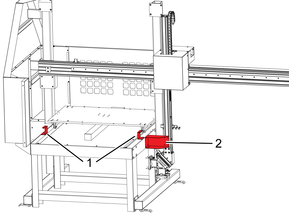
Remove the shipping brackets that are shown in red in the image.

Electrical Installation

1

Install the AU and AV axes amplifiers in the respect with the decal labels on the amplifier fan bracket

Note: AU axis amplifier [1] shown on the picture

2

If the machine was built with the single lead DC buss cable (33-04901B) you will need to replace it with the dual lead DC BUS cable (33-0052C) provided with the kit

Before working on this cable, power the machine OFF and allow the Vector Drive capacitors to discharge until the red light [1] on the Vector Drive is OFF

Remove the old cable that supplies DC voltage from the Vector Drive terminals 2 and 3 to the amplifiers

Install the new dual lead DC BUS cable (33-0052C) as follows:

  • Connect the end with the ring terminals [2] to the terminal 2 and 3 on the Vector Drive:
    • The white lead that is labeled TB2 "+" to the terminal 2
    • The black lead that is labeled TB3 "-" to the terminal 3

Route the longer cable through the fan bracket under the amplifiers and connect it to the "+" H.V. and the "-" H.V. terminals on the left most servo amplifier [3] as labeled

Connect the remaining cable to the "+" H.V. and the "-" H.V. terminals on the right most servo amplifier [4] as labeled


3

Route the AU and AV axes power cables through the opening on the bottom of the control cabinet

Connect the power cable leads to the high voltage terminals 
 Note: The AV axis power cable leads are labeled PH-A, PH-B and PH-C due to a different color scheme. Connect as follows::

  • red to RED [1]
  • white to WHT [2]
  • black to BLK [3]
  • PH-A to RED
  • PH-B to WHT
  • PH-C to BLK

Connect the ground wire [4] to the bracket for the amplifier fan

Find the high-voltage terminals [5] on the nearest amplifier

Find the high-voltage terminals [7] on the amplifier

Install the jumpers [6] from the installation kit between these terminals

Connect the black wire to -H.V. Connect the red wire to +H.V.

4

Connect the current command cables to the connector near the top of the each amplifier [1]

Connect the other ends of the cables to the AMPLIFIER COMMAND outputs on the NGC PCB [2] as follows:

  • AU axis to the output 13
  • AV axis to the output 15

Route the U and V axes encoder cables through the opening on the bottom of the control cabinet and connect them to the ENCODER inputs on the NGC PCB [3] as follows:

  • AU axis to the input 13
  • AV axis to the input 15

5

Install New Bracket in Electrical Cabinet

Machines with a Wye/Delta [1] in the electrical cabinet will need to remove it before installing the new bracket [2] using the 10-32 screws [3] in the kit.

6

At this point if applicable, re-install the Wye/Delta [1] and then install the C-APL power supply and CAN board assembly [2] as shown next to the vector drive.

7

If the machine does not have an I/O hinge door already installed, install it at this time.

Install the SMTC PCB [1] onto the SIO door using the standoffs [2] and the screws [3].

8

Remove the Jumper at P12 on the I/O board.

Connect the rotators cable 33-1176 [1] to P12 on the I/O board.

Connect the solenoids cable 33-1172 [2] to P3 on the SMTC board.

Connect cable 33-3333 [3] from P4 on the SMTC boards to P7 on the PSUP Board.

Connect cable 33-1518 [4] from P1 on the SMTC board to P15 on the I/O board.

Connect cable 33-1760A [5] from P2 on the SMTC board to P18 on the PSUP board.

Connect cable 33-1171 [6] from P5 on the PSUP to the C-APL power supply.

Connect the C-APL motor cable 33-1177 [7] to J6 of the C-APL CAN board.

Connect cable 33-5308 [8] from J1 on the C-APL CAN board to J2 on the I/O board.

Note: If the machine is powered by a single phase input, cable 33-7180 is needed to connect power to P5/P6/P7 on the PSUP board from P3 on the PSUP board.

Note: If this machine is equipped with other CAN systems, visit the CAN Systems Troubleshooting Guide for where the Compact APL falls in the CAN sequence.

9

Refer to this step if your machine has a light curtain or area scanner.

Install the relay bracket [1] to the LVPS bracket.

Install the safety relay [2] onto its bracket [1] as shown.

Important: If the machine is equiped with an Autodoor, the power supply and CAN board assembly will need to be removed to install the safety relay bracket.

10

Refer to this step if your machine has a light curtain or area scanner.

Connect the Area Scanner or Light Curtain Receiver Input cable to the safety relay connector [9].

If using the Light Curtain, connect the Light Curtain Emitter Input to the safety relay connector [10].

11

Refer to this step if your machine has a fence and uses an interlock.

The fence interlock cable 33-0734 [9] should be connected to P1 and P9 on the I/O board.

Safety Device Install

IMPORTANT: DO NOT OPERATE THE C-APL UNTIL YOU HAVE PROPERLY CONFIGURED AND TESTED THE OPERATION OF THE SAFETY DEVICE.

Light Curtain:

If the machine came equipped with the light curtain option, the light curtain needs to be installed. Follow the procedure below for installation: 

Light Curtain Installation

Robot Fence:

If the machine came equipped with the fence option, the robot fence and door interlock assembly need to be installed to machine. Follow the procedure below for installation:

Haas Compact Automatic Parts Loader (C-APL) - Fence Installation

Area Scanner:

If the machine came equipped with the area scanner option, the area scanner needs to be installed and configured to the space. Follow the procedure below for installation: 

Area Scanner Installation

First Power On

1

Important: For the C-APL Field Install kit it is required to have patch files loaded to the machine.  Go to HBC to download the latest C-APL patch files from service kit 93-1001107 before continuing.

Note: The control needs to be in Service Mode to access the Factory Settings menu

E-STOP the machine

Change parameter 9015.001 CAN NODE 15 ENABLE to TRUE

Change parameter 2191 LIGHT CURTAIN TYPE to LC_TYPE_1

Set the setting 372 PARTS LOADER TYPE to COMPACT

Set the setting 375 APL GRIPPER TYPE to Dual Extender Gripper

Set the Setting 376 LIGHT CURTAIN ENABLE to ON

Keep the E-STOP depressed and power the machine OFF

2

Power Up the machine with the E-STOP depressed

Before releasing the E-STOP, navigate to the CURRENT COMMANDS screen and make sure that the AUTOMATIC PART LOADER tab is visible.

Navigate to the ALARMS AND MESSAGES and make sure that there are no active alarms associated with the AU and AV axes

Release the E-STOP and zero return the machine

Set Grid Offsets

1

Set Grid Offsets for AU and AV axes:

Zero Return AU and AV

Go to the Diagnostics Tab> Parameters > Factory Settings

  • Press AU + F4
  • Press AV + F4

Workholding

Follow the link below for workholding installation instructions.

Haas Tooling and Workholding - Service Manual

Disable the APL

Jog to a safe location

To disable the APL to run the machine in stand-alone mode. Press [SETTING]. Change the following Settings:

  • 372 Parts Loader Type to 0: None
  • 376 Light Curtain Enabled to Off

Change parameter 9015.001 CAN NODE 15 ENABLE to FALSE.

Feedback

Recently Viewed Items

You Have No Recently Viewed Items Yet

Feedback
Haas Logo

美元价格不包括关税、报关费用、保险费、增值税及运费。
USD prices DO NOT include customs duty, customs fees, insurance, VAT, or freight.

人民币价格包含关税、报关费用、货运保险和增值税, 但不包括运费。
CNY prices include customs duty, customs fees, insurance, and VAT. DOES NOT include freight.

Haas Delivered Price

This price includes shipping cost, export and import duties, insurance, and any other expenses incurred during shipping to a location in France agreed with you as a buyer. No other mandatory costs can be added to the delivery of a Haas CNC Product.

KEEP UP WITH THE LATEST HAAS TIPS AND TECHNOLOGY...

Sign up now!   

HAAS TOOLING ACCEPTS THE FOLLOWING:

  • Service & Support
  • Owners
  • Request Service
  • Operator Manuals
  • Haas Parts
  • Rotary Repair Request
  • Pre-Install Guides
  • Shopping Tools
  • Build & Price a New Haas
  • Available Inventory
  • The Haas Price List
  • CNCA Financing
  • About Haas
  • DNSH Statement
  • Careers
  • Certifications & Safety
  • Contact Us
  • History
  • Terms & Conditions
  • Haas Tooling Terms & Conditions
  • Privacy
  • Warranty
  • Haas Community
  • Haas Certification Program
  • Haas Motorsports
  • Gene Haas Foundation
  • Haas Technical Education Community
  • Events
  • Join the Conversation
  • Facebook
  • X
  • Flickr
  • YouTube
  • LinkedIn
  • Instagram
  • TikTok
© 2025 Haas Automation, Inc – CNC Machine Tools

This site is protected by reCAPTCHA and the Google Privacy Policy and Terms of Service apply.

2800 Sturgis Rd., Oxnard, CA 93030
Toll Free: (888) 817-4446 / Fax: 805-278-8554