-
machines
-
Vertical Mills
Vertical Mills
-
Multi-Axis Solutions
Multi-Axis Solutions
-
Lathes
Lathes
-
Horizontal Mills
Horizontal Mills
-
Rotaries & Indexers
Rotaries & Indexers
-
Special Series
Special Series
-
Automation Systems
Automation Systems
-
Desktop Machines
Desktop Machines
-
Shop Equipment
Shop Equipment
-
Fabrication Machines
Fabrication Machines
SHOPPING TOOLSWANT TO TALK TO SOMEONE?A Haas Factory Outlet (HFO) can answer your questions, and walk you through your best options.
CONTACT YOUR DISTRIBUTOR > -
Vertical Mills
-
Options
-
/2026-04-VOP-SquareComponent.jpg/_jcr_content/renditions/cq5dam.thumbnail.319.319.png) Value Option Packages
Value Option Packages
Value Option Packages
Value Option Packages -
 Spindles
Spindles
Spindles -
 Tool Changers
Tool Changers
Tool Changers -
 4th- | 5th-Axis
4th- | 5th-Axis
4th- | 5th-Axis -
 Turrets & Live Tooling
Turrets & Live Tooling
Turrets & Live Tooling -
 Probing
Probing
Probing -
 Chip & Coolant Management
Chip & Coolant Management
Chip & Coolant Management -
 The Haas Control
The Haas Control
The Haas Control -
 Product Options
Product Options
Product Options -
 Tooling & Fixturing
Tooling & Fixturing
Tooling & Fixturing -
 Workholding
Workholding
Workholding -
 5-Axis Solutions
5-Axis Solutions
5-Axis Solutions
SHOPPING TOOLSWANT TO TALK TO SOMEONE?A Haas Factory Outlet (HFO) can answer your questions, and walk you through your best options.
CONTACT YOUR DISTRIBUTOR > -
-
Why Haas
Discover the Haas Difference
-
Service
Welcome to Haas Service
- Videos
-
SHOPPING TOOLSWANT TO TALK TO SOMEONE?
A Haas Factory Outlet (HFO) can answer your questions, and walk you through your best options.
CONTACT YOUR DISTRIBUTOR > -
- Haas Tooling
- Haas Service Parts


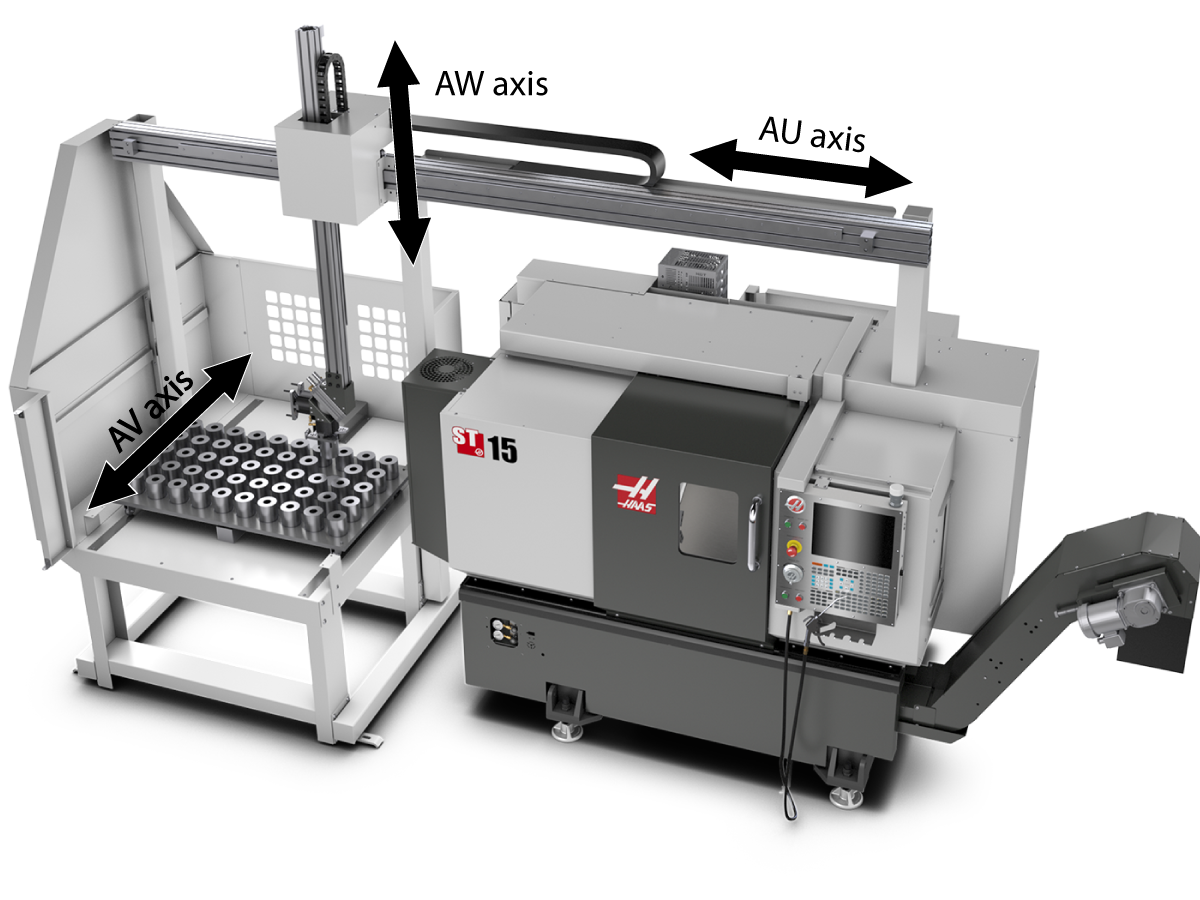
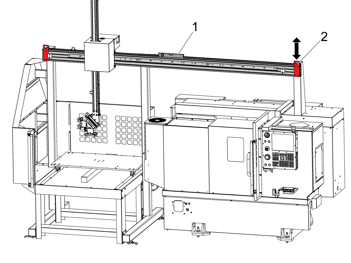
---vertical---installation/APL-Axis-Directions.png)
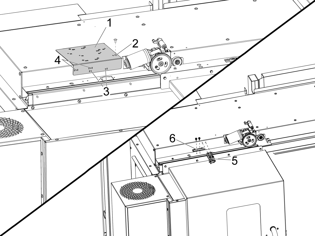
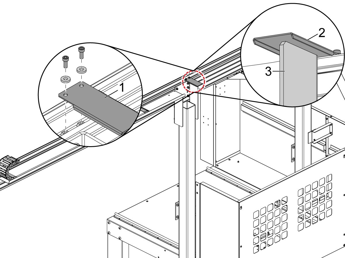
---vertical---installation/Install-Prox-Switch-Bracket.png)
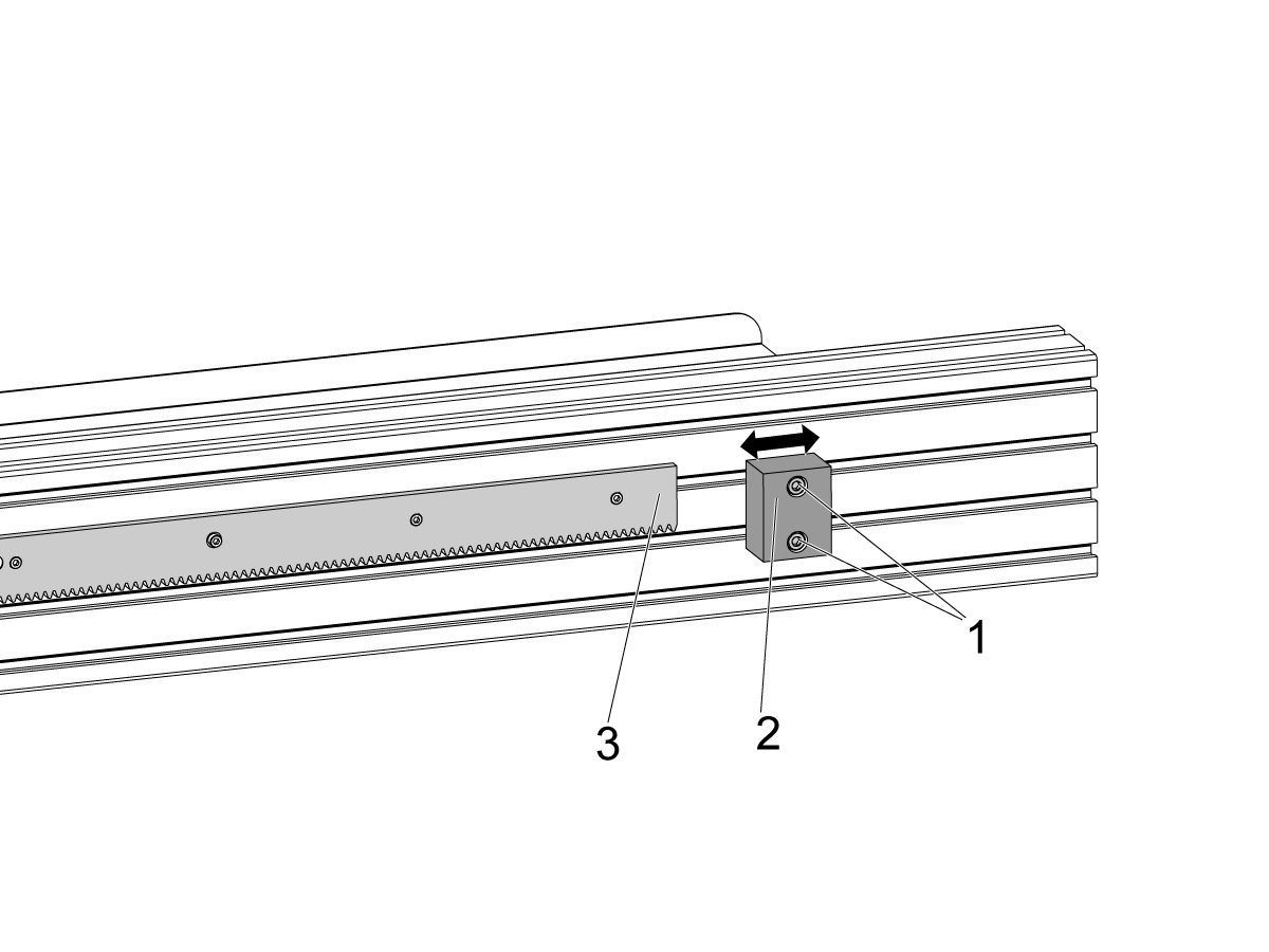
---vertical---installation/Drill-Autodoor-Flag_1.png)
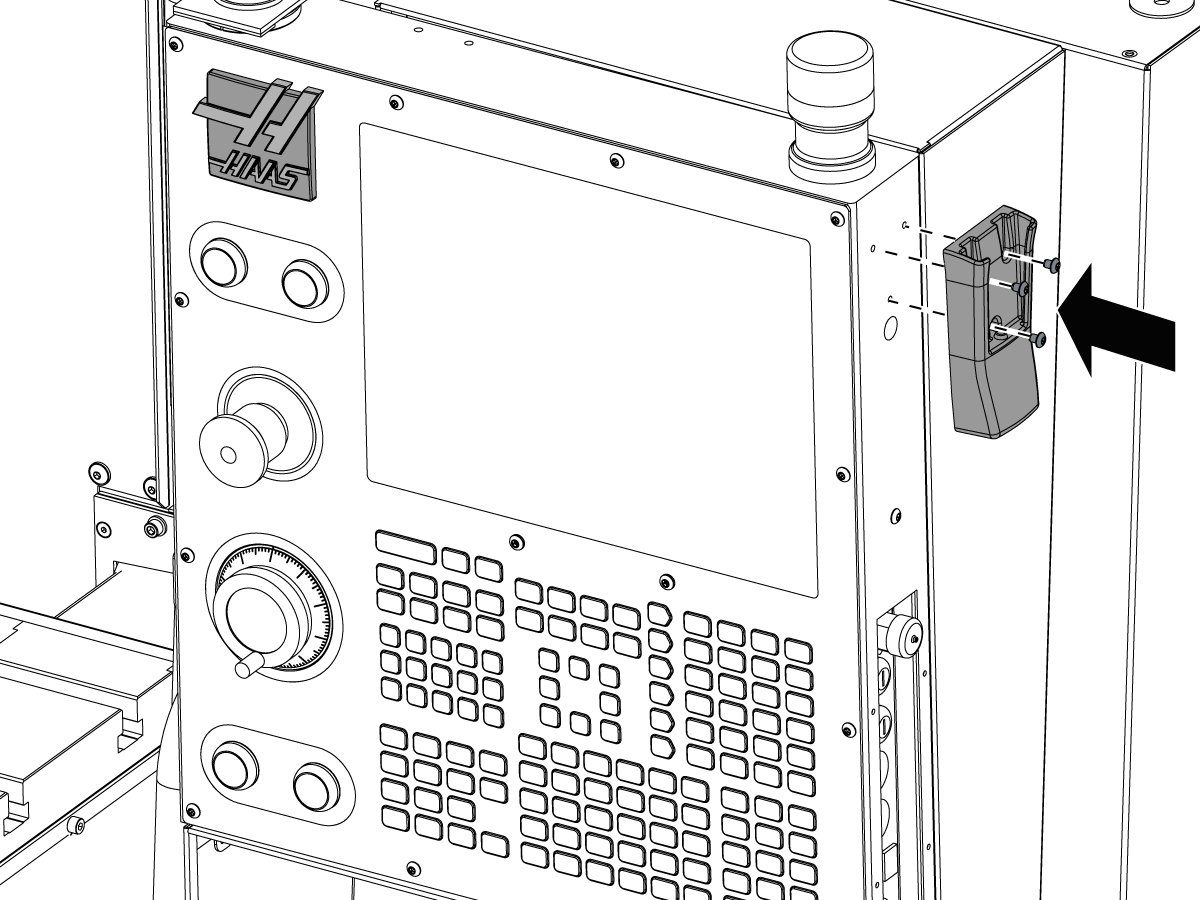
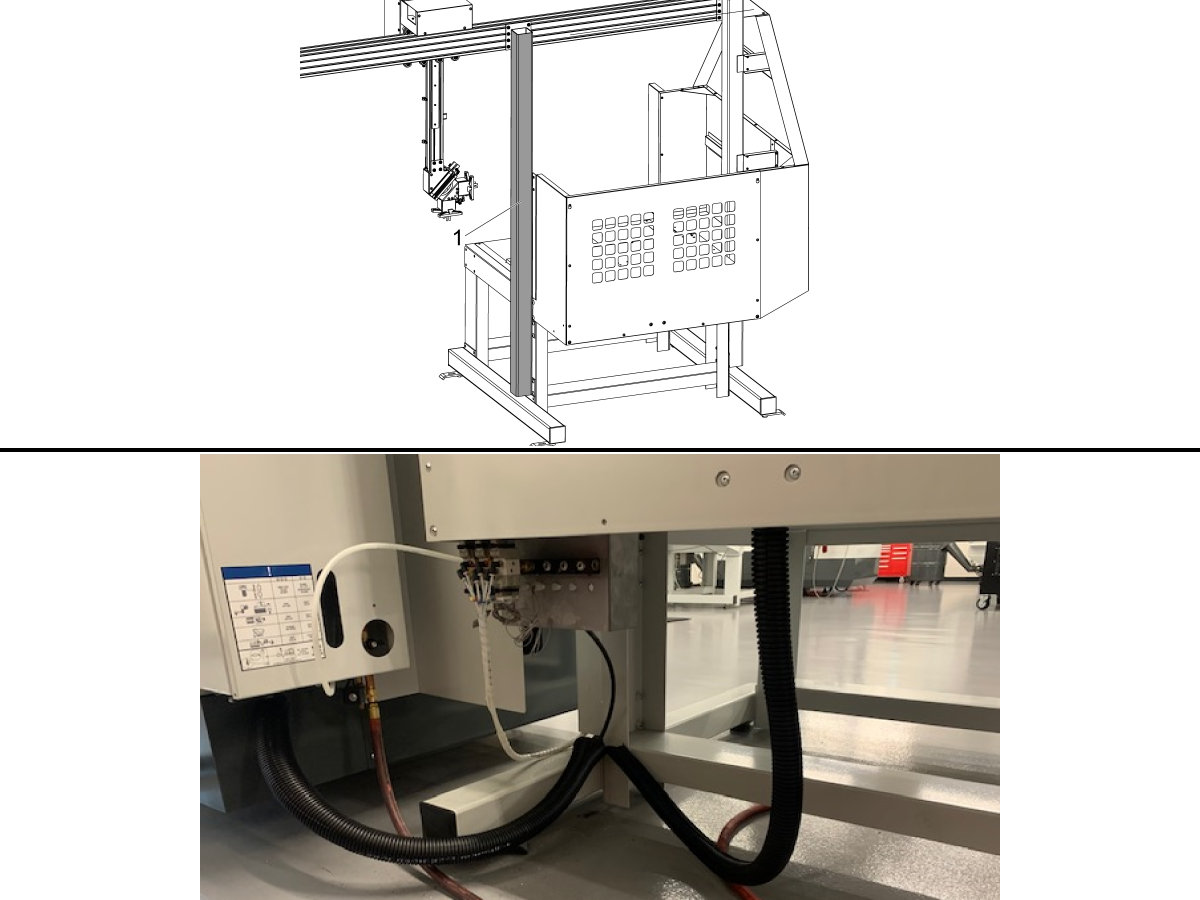
---vertical---installation/Move-Air-Gun.png)
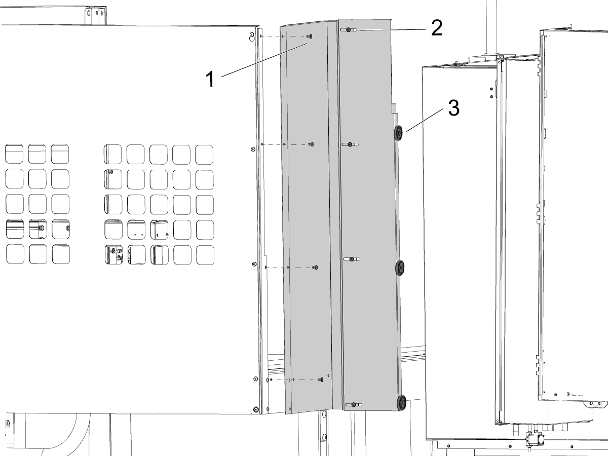
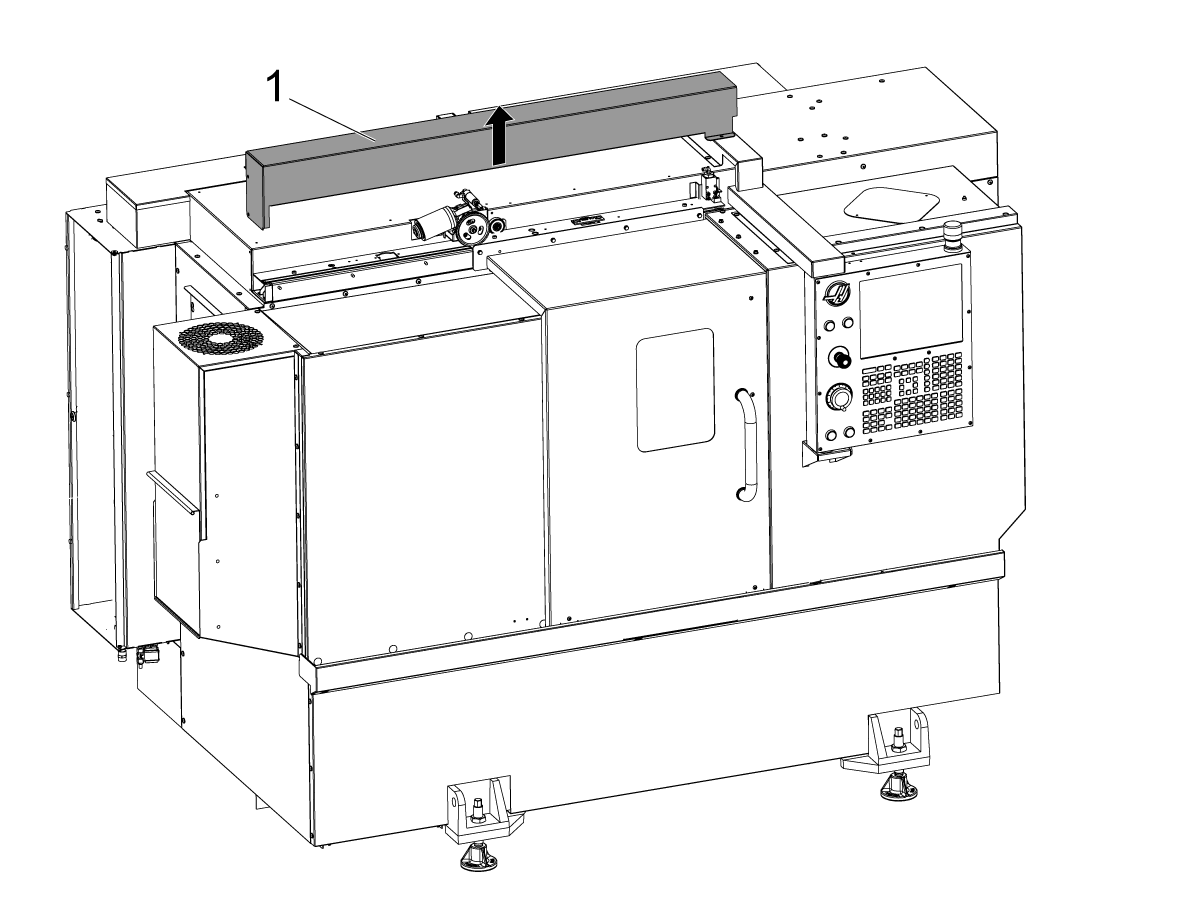
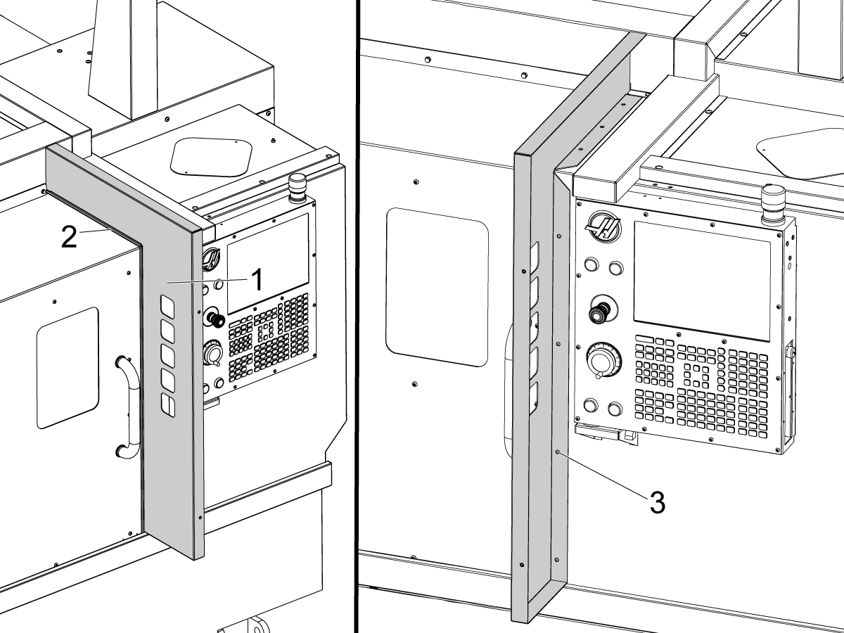
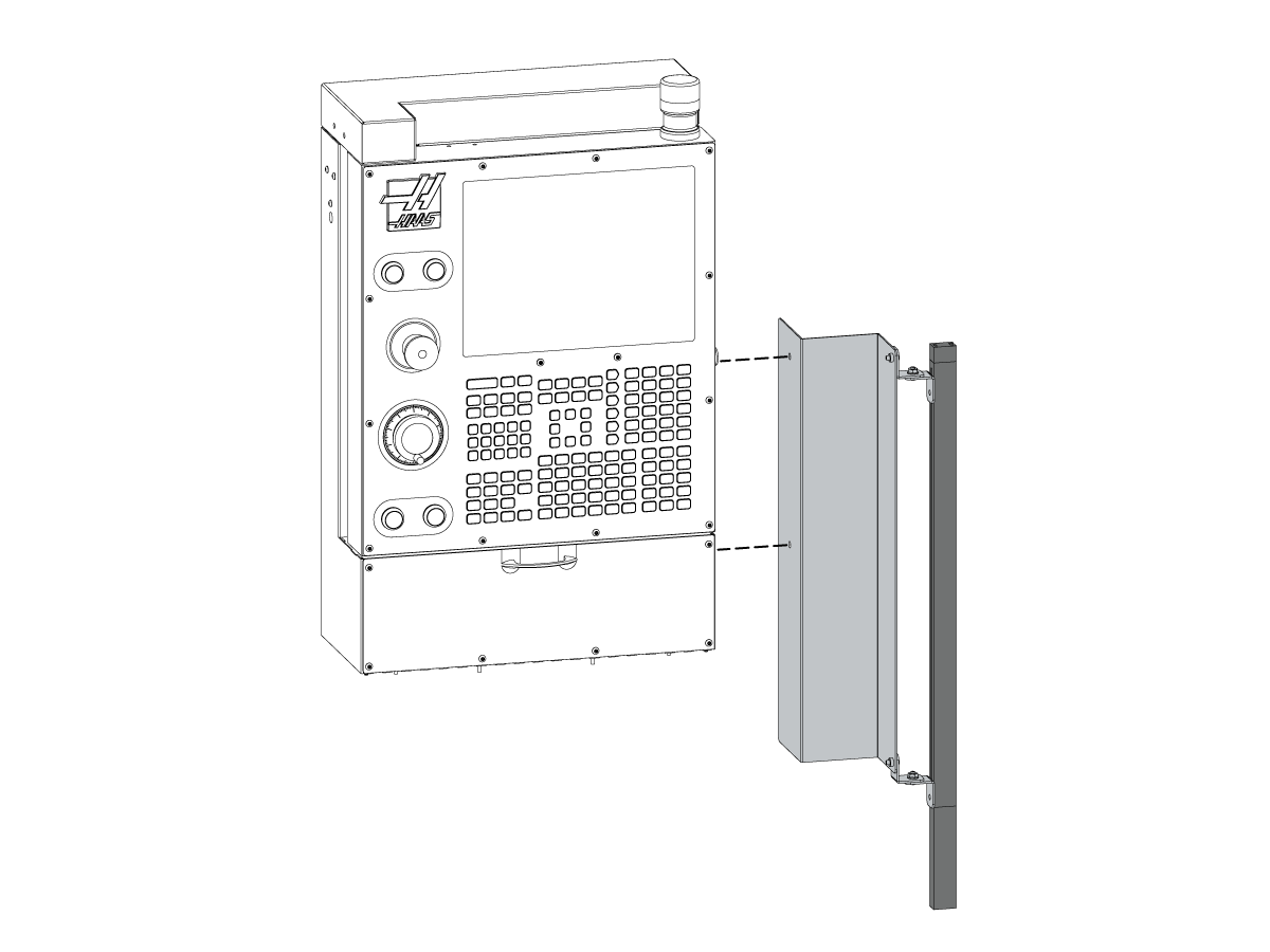
---vertical---installation/Install-Rear-Panel.png)
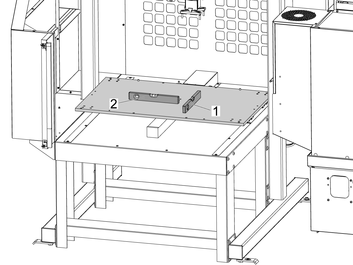
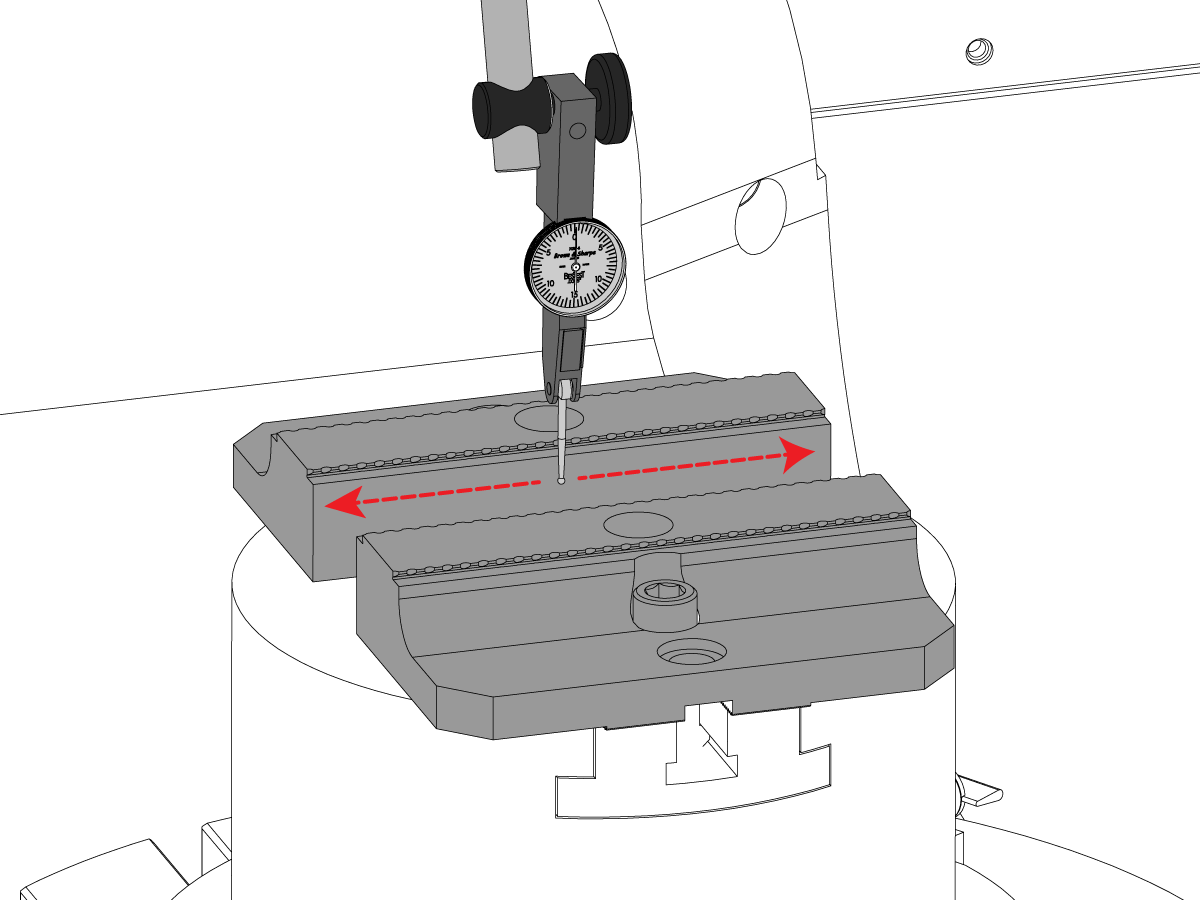
---vertical---installation/Level-the-Mill-APL.png)
---vertical---installation/Remove-Arm-Shipping-Bracket.png)
---vertical---installation/Remove-Table-Shipping-Brackets.png)
---vertical---installation/Remove-The-AU-AW-axis-shipping-brackets.png)
---vertical---installation/Light-Curtain-Hole-Pattern.png)
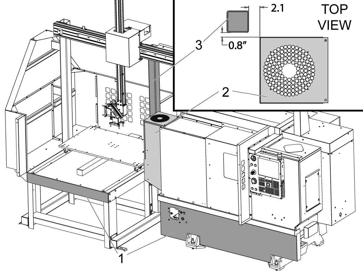
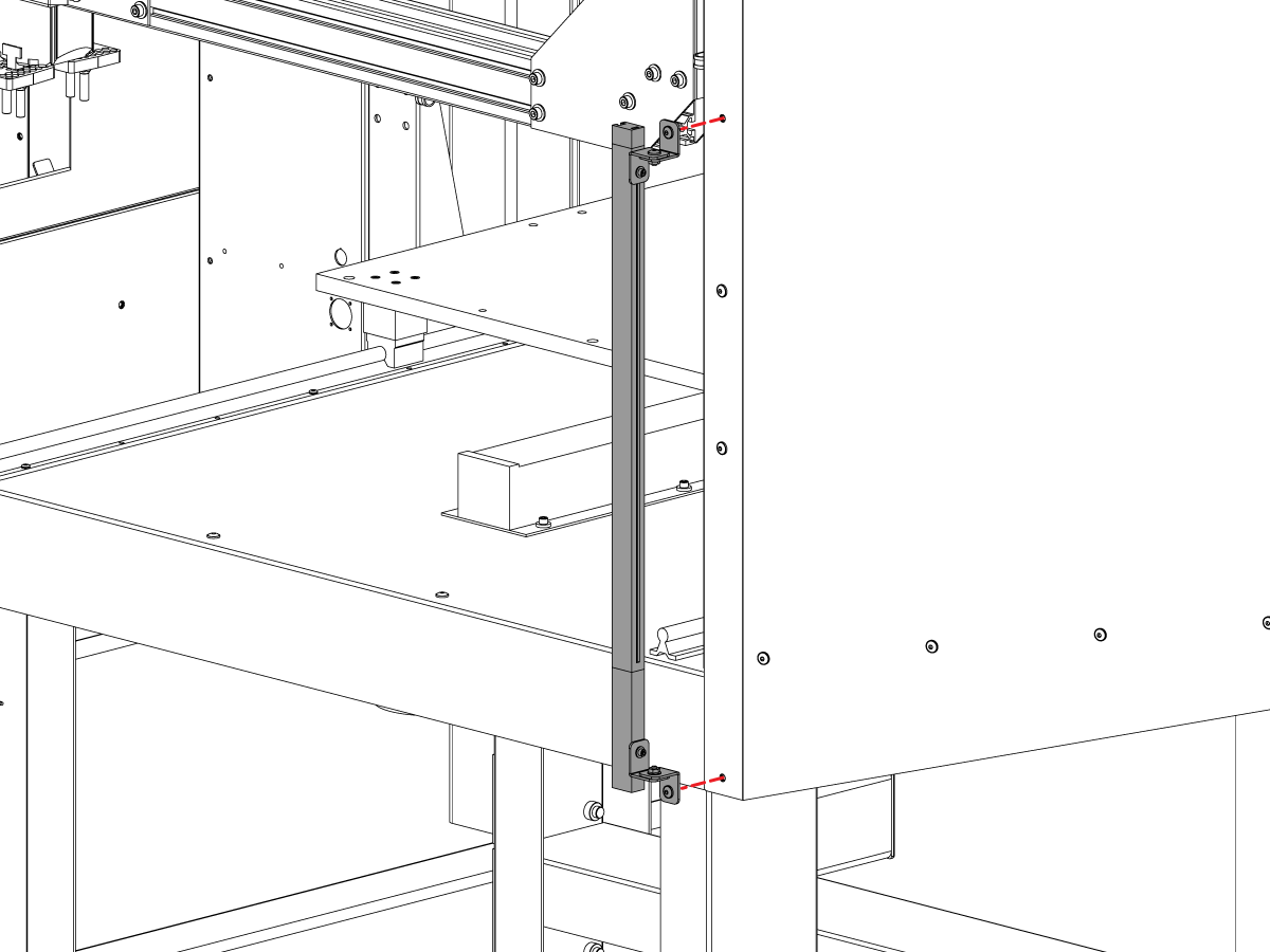
---vertical---installation/Side-Panel-Hole-Pattern.png)
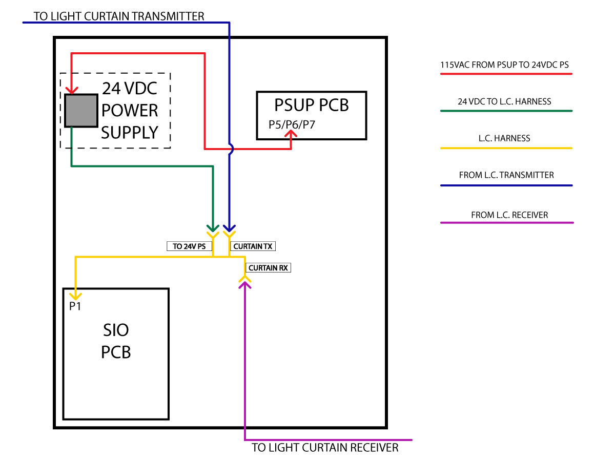
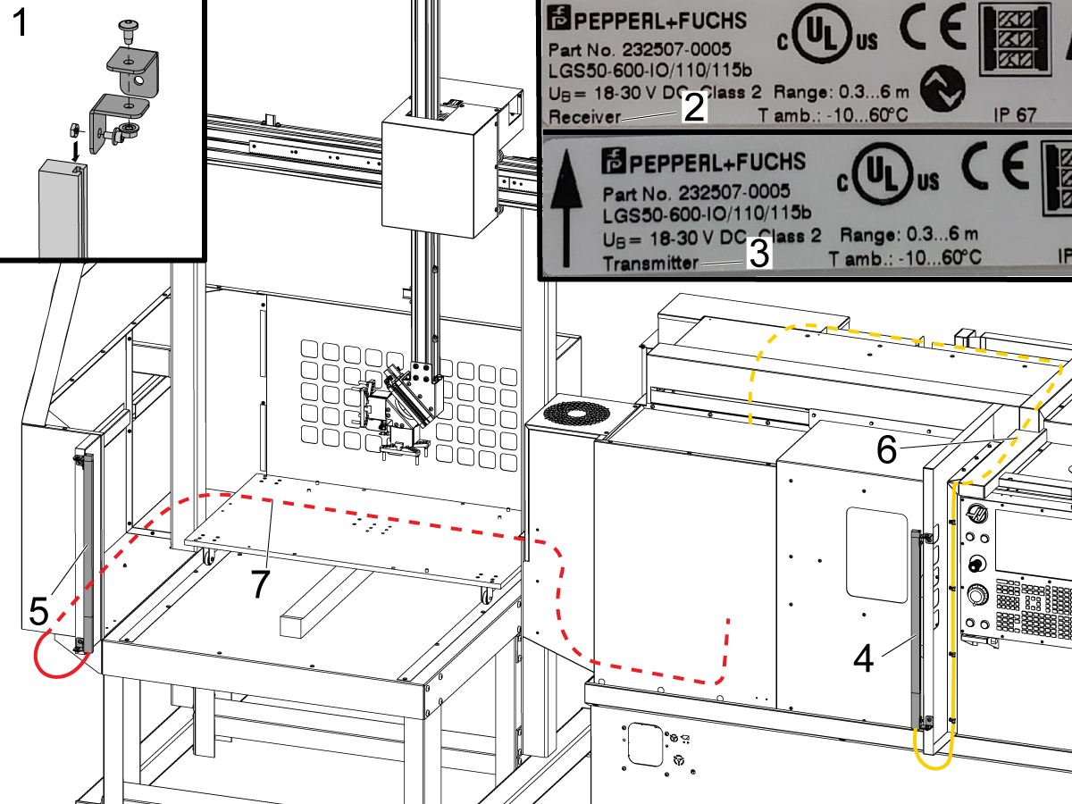
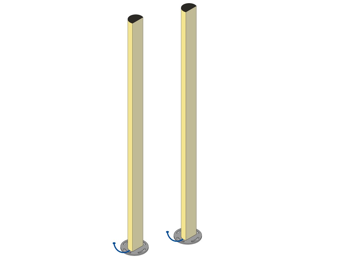
---vertical---installation/Light-Curtain-Installation.png)
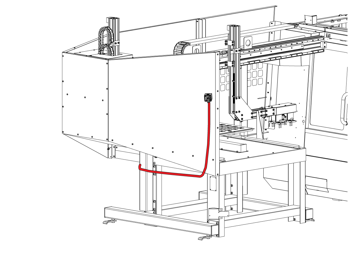
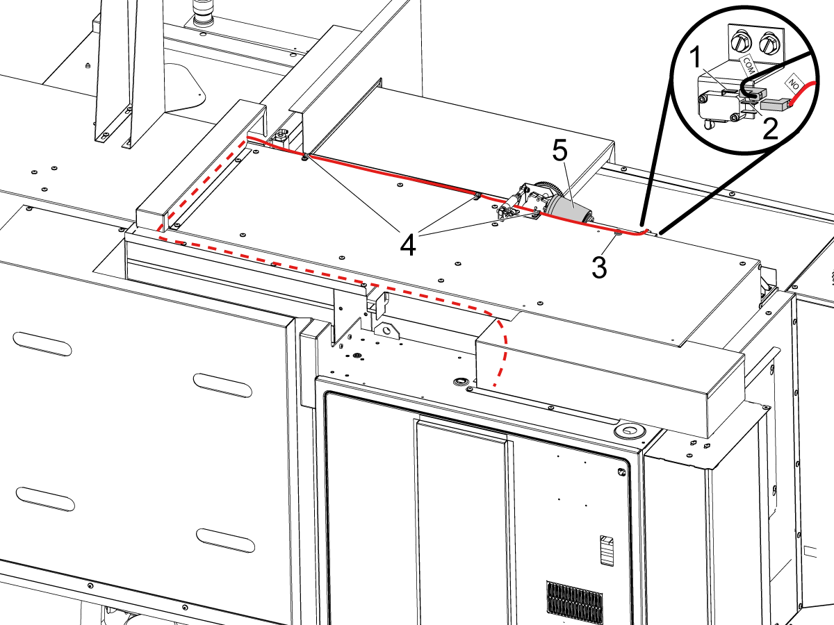
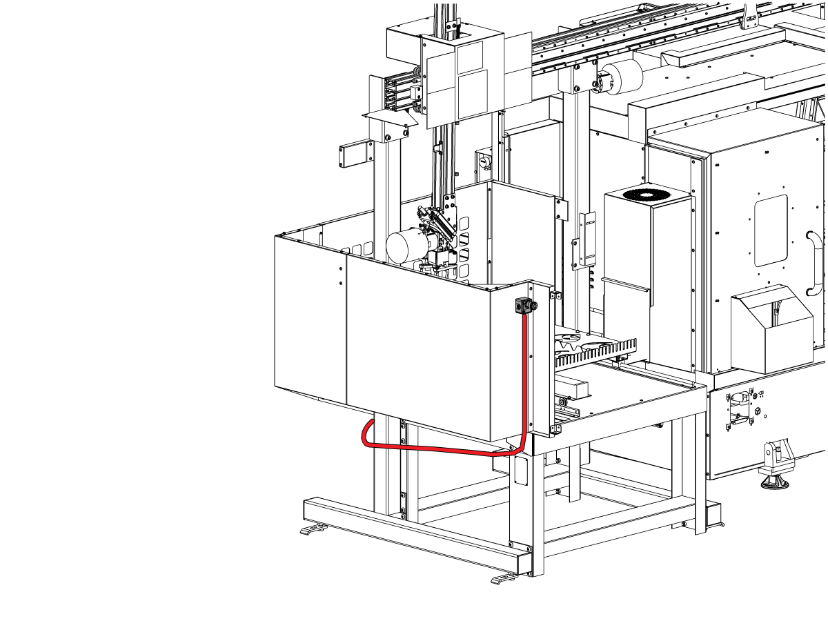
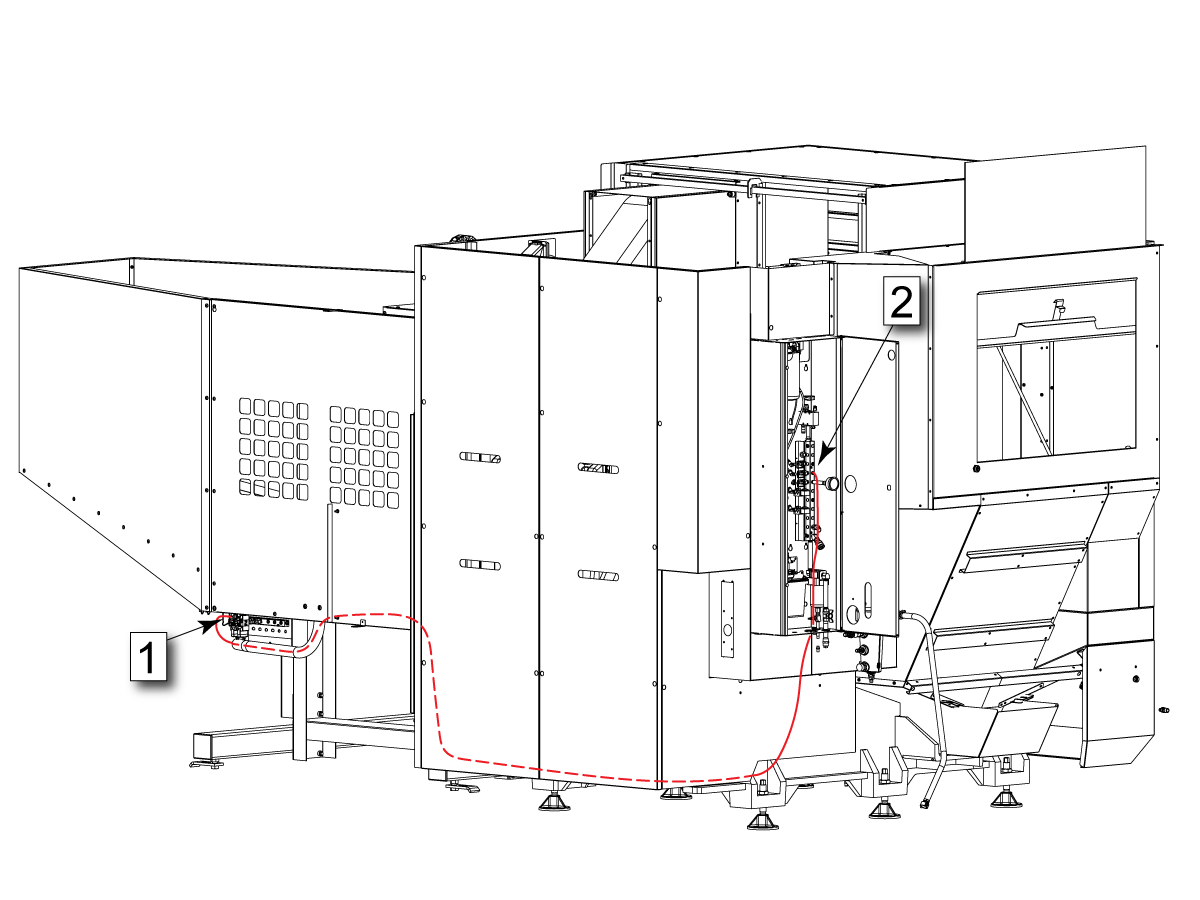
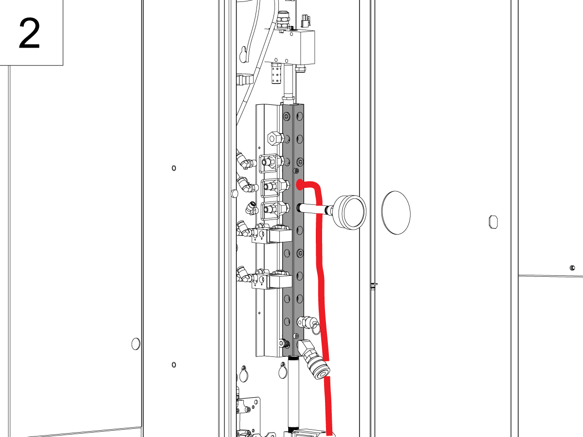
---vertical---installation/Route-Cables_1.png)
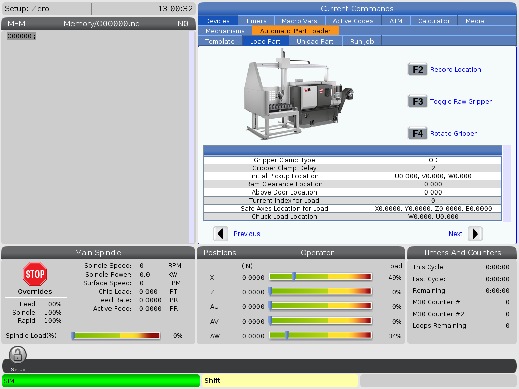
---vertical---installation/Currents-Comments-APL-TAB.png)
---vertical---installation/APL-Grid-Offset.png)
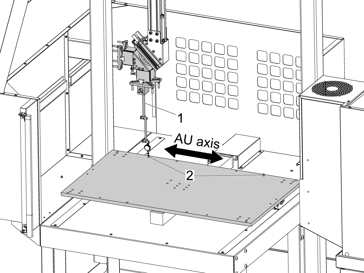
---vertical---installation/Align-AU-Axis.png)
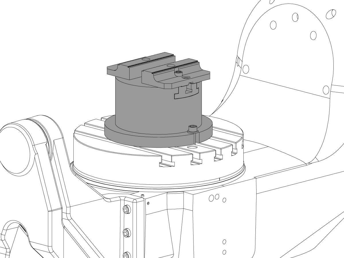
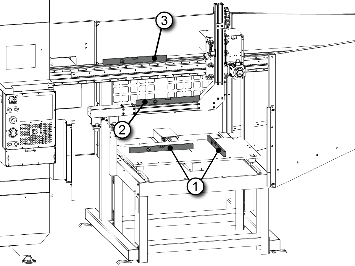
---vertical---installation/Align-APL-Grippers-to-Vice.png)


---vertical---installation/APL-Tool-Change-Offset.png)
---vertical---installation/2019-10-08_15h56_48.jpg)
---umc---installation/umc_apl_90_degree_control_cabinet_alignment.png)
---umc---installation/foot-print-reduction-placement_measurment.png)
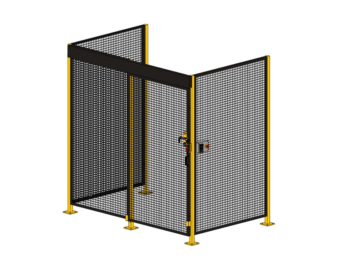
---umc---installation/new-fence-enclosure-panel-ce-machines.png)
---umc---installation/umc_apl_panel_to-electrical.png)
---umc---installation/foot-print-reduction-new-enclosure-panel.png)
---umc---installation/umc_90_degree_route_conduit.png)

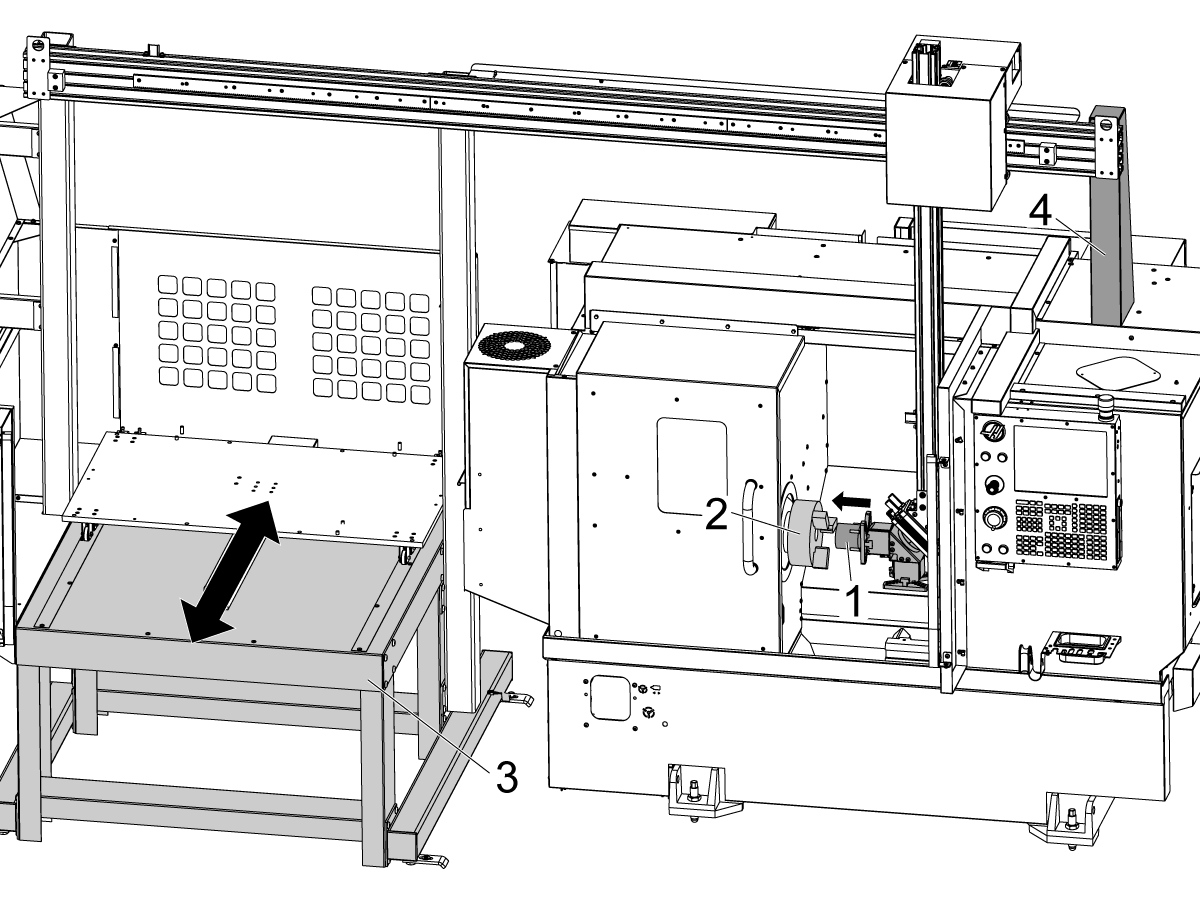
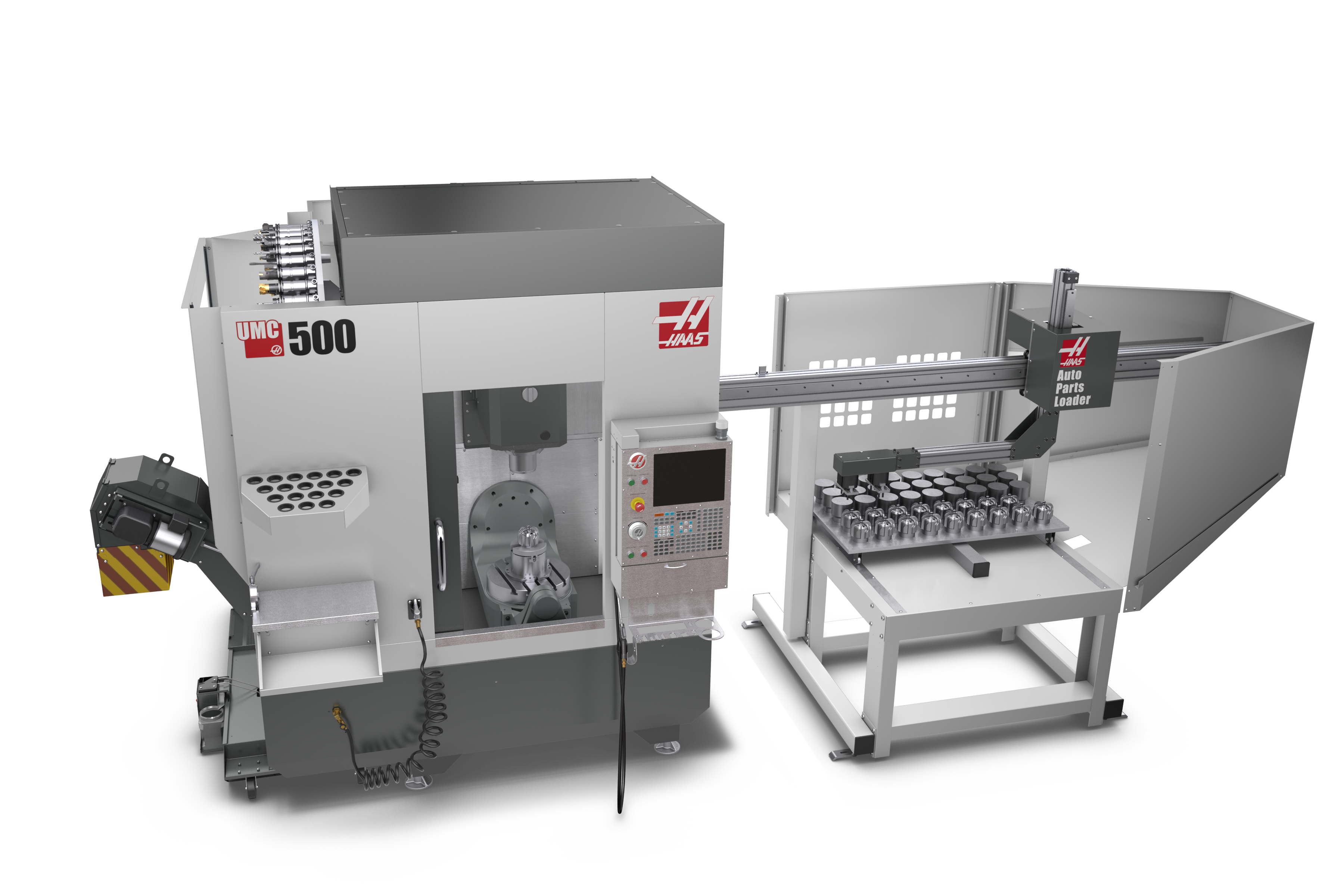
---installation/c-apl_intro.png)
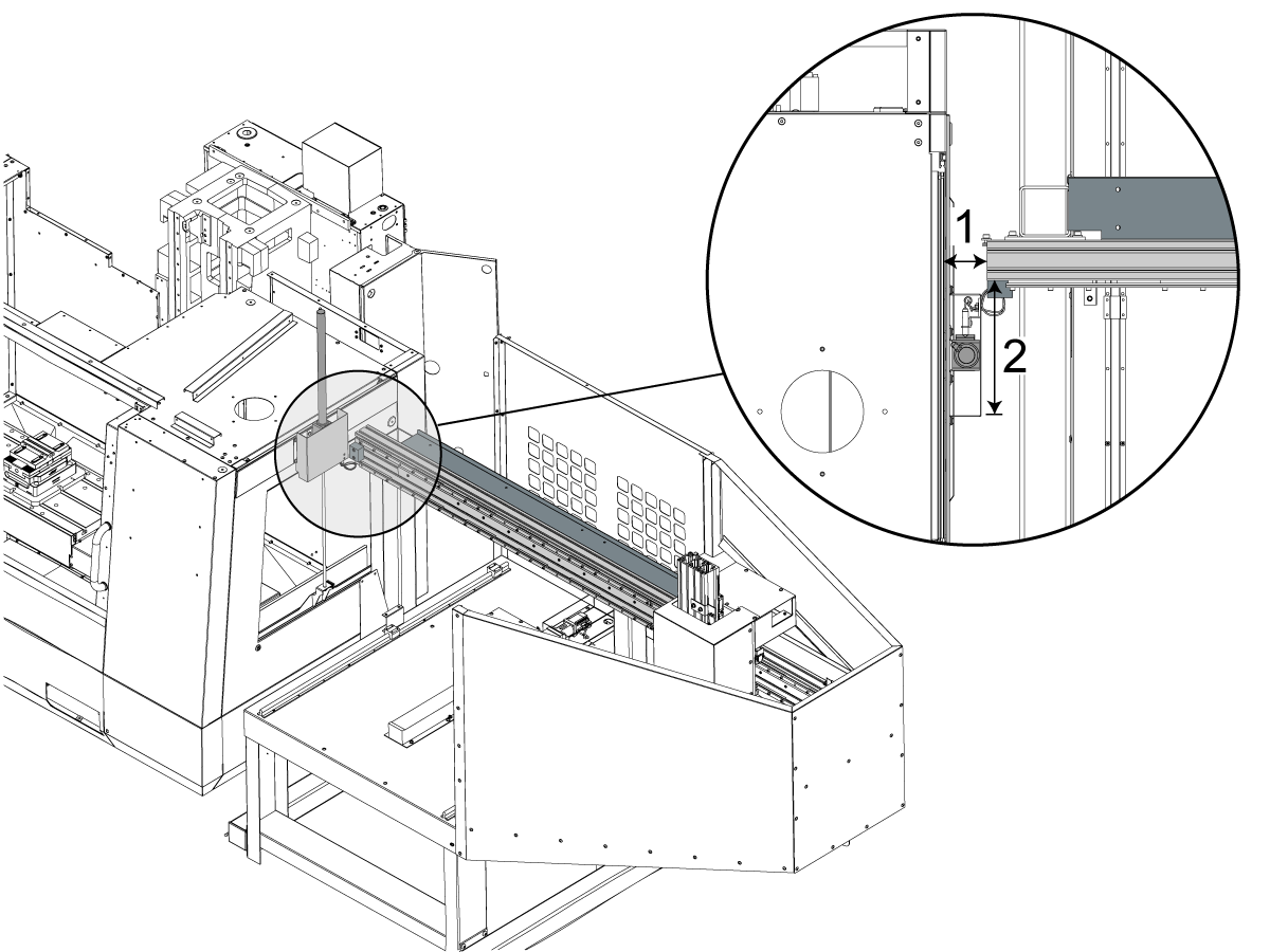
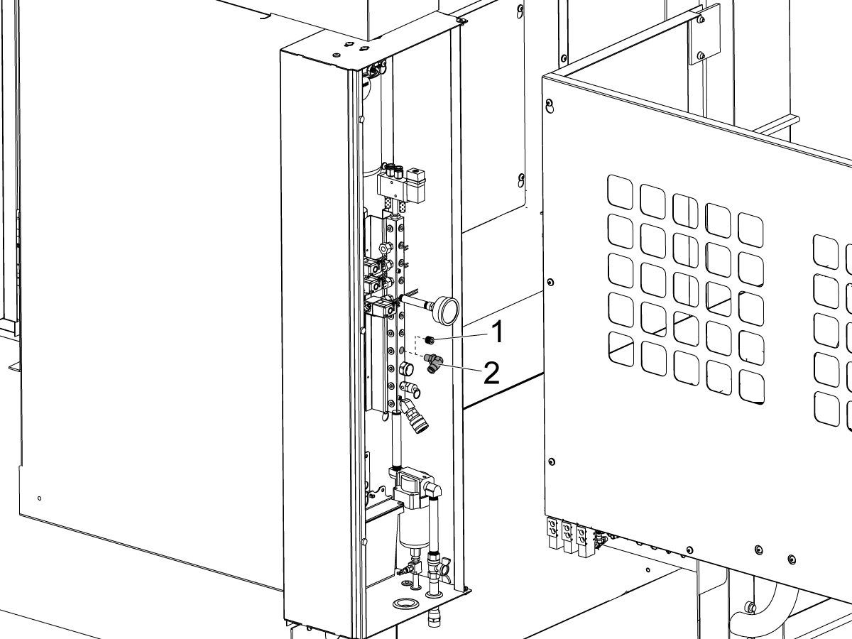
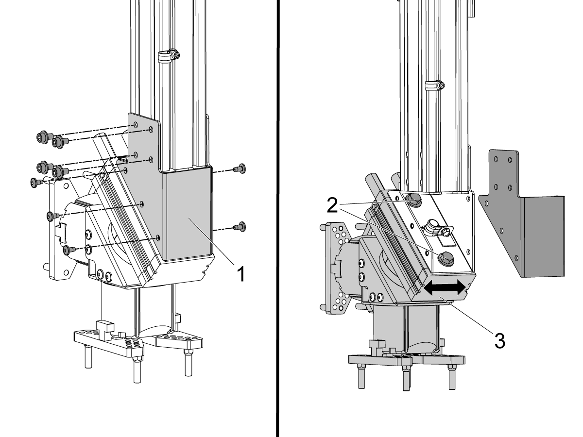
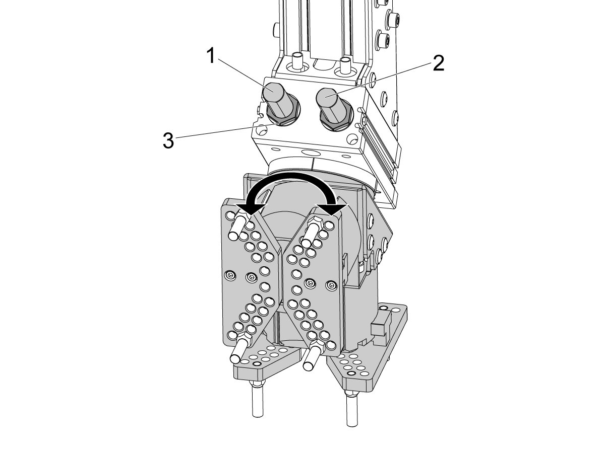
---installation/adjust-air-cylinder.png)
---installation/c-apl_updated_feet_attachment.png)
---installation/c-apl_height_adjustment.png)
---installation/attach-anchor-sheet-metal.png)
---installation/updated-feet-attachment.png)
---installation/attach-anchor-sheet-metal-update.png)
---installation/locating-bracket-umc350-placement.png)
---installation/locating-bracket-DM-placement.png)
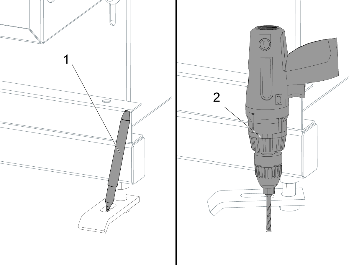
---installation/locating-bracket-vf-placement.png)
---installation/c-apl-locating-bracket-on-mm.png)
---installation/level_compact_apl.png)
---installation/update-anchoring.png)
---installation/shipping-brackets.png)
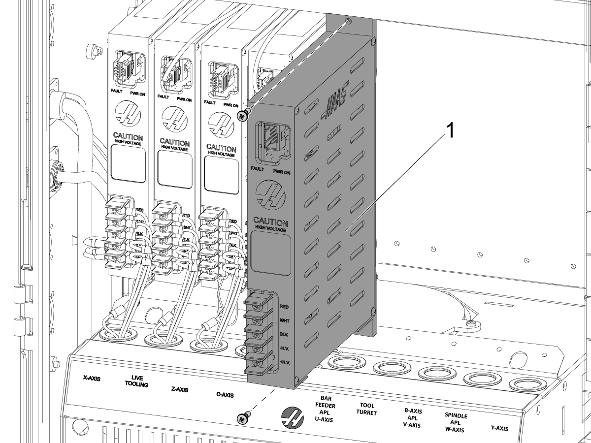
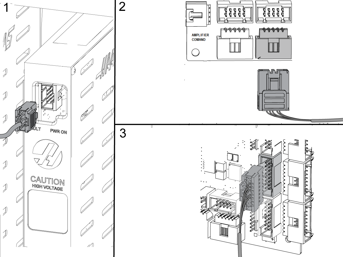
---installation/remove-wye-delta-and-attach-new-bracket.png)
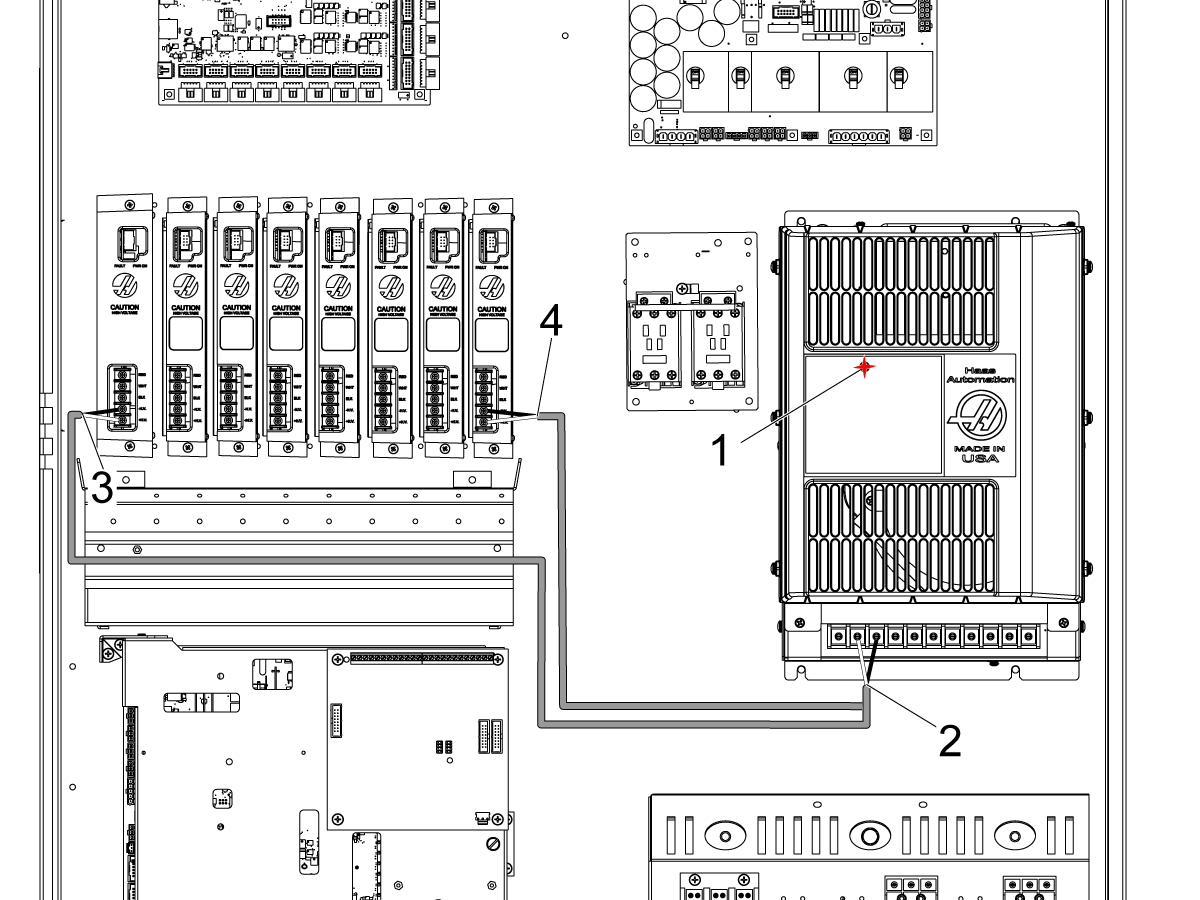
---installation/attach-wye-delta-and-ps-with-can-board.png)
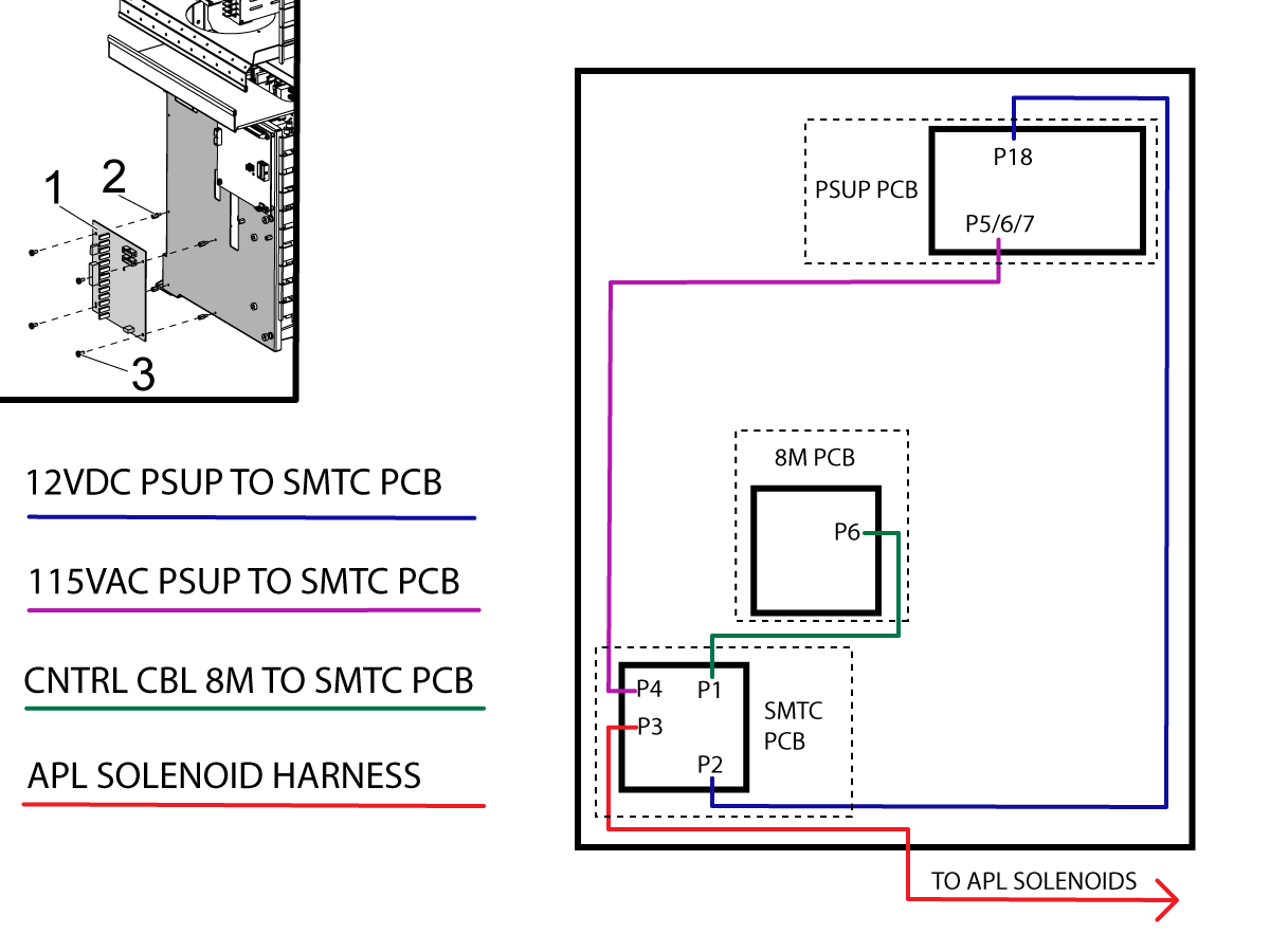
---installation/smtc-board-location.png)
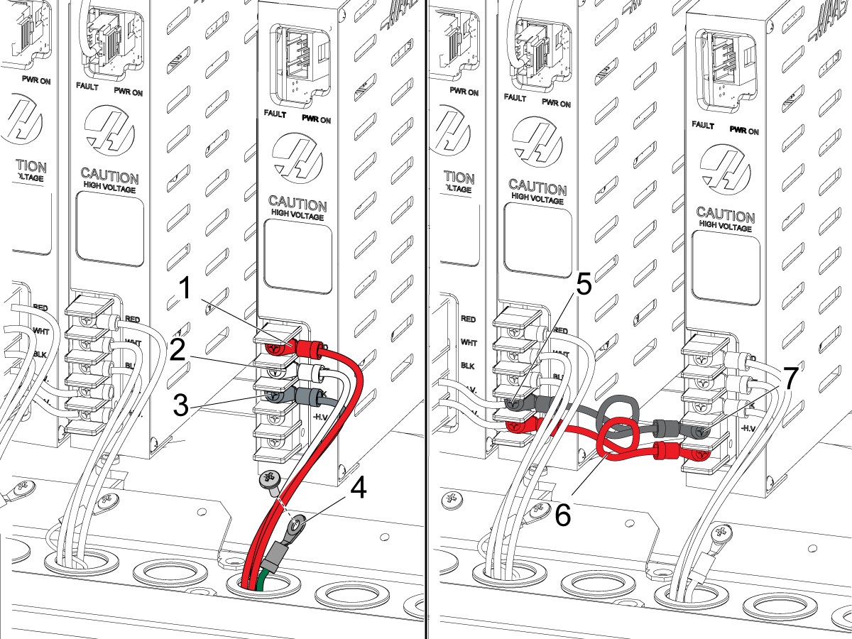
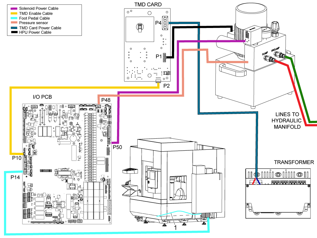
---installation/wire-diagram.png)
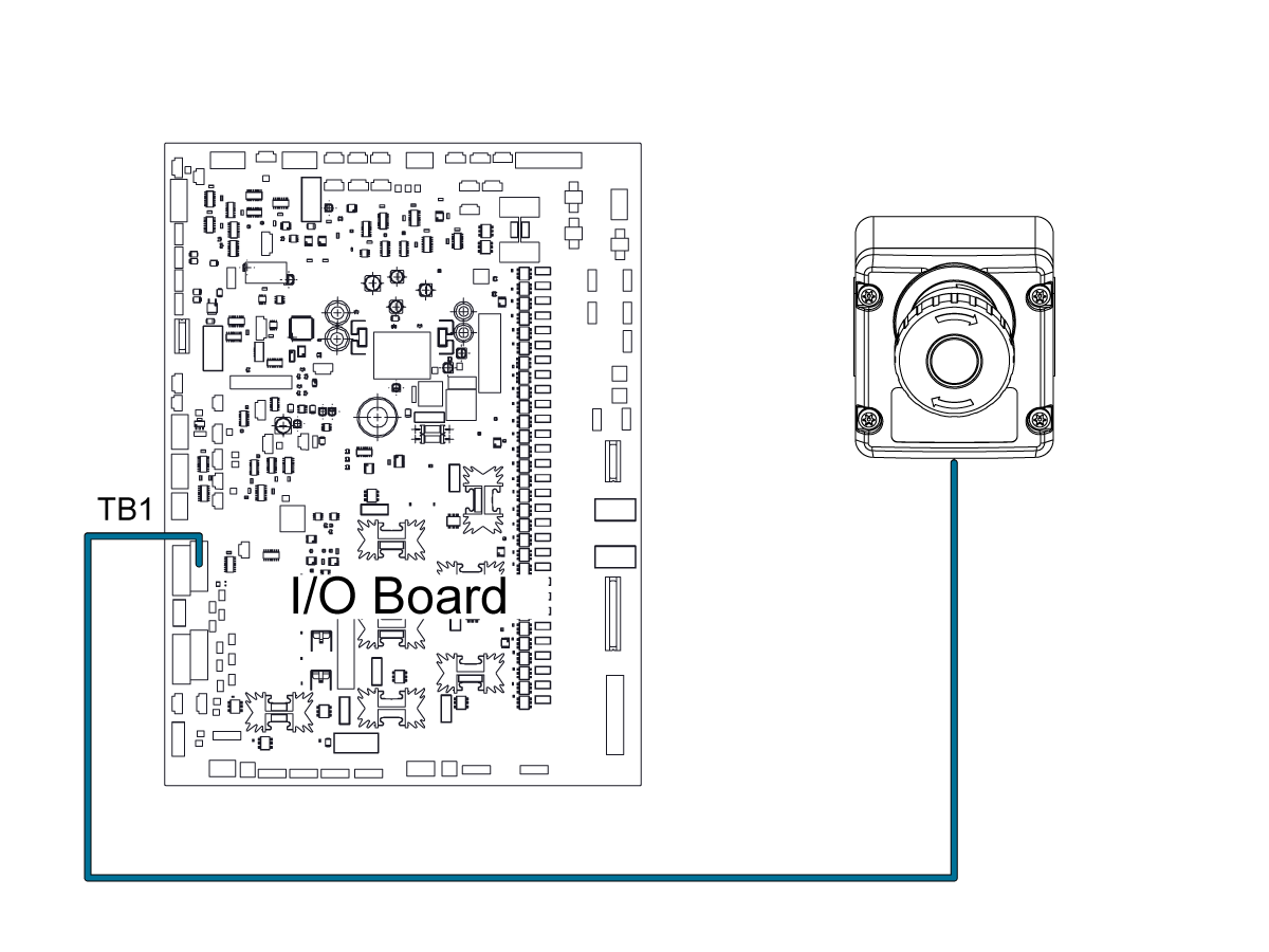
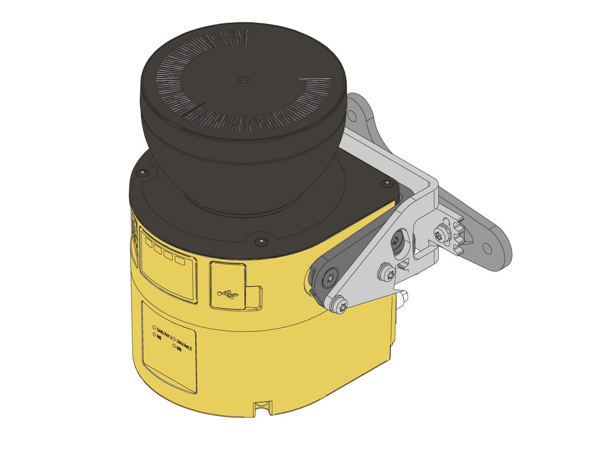
---installation/install-safety-relay.png)
---installation/safety_device_wire_diagram_ce.png)
---installation/fence_interlock_wire_diagram.png)
---installation/current-commands-CAPL.png)